Electrical System Wiring Procedure
12
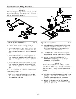
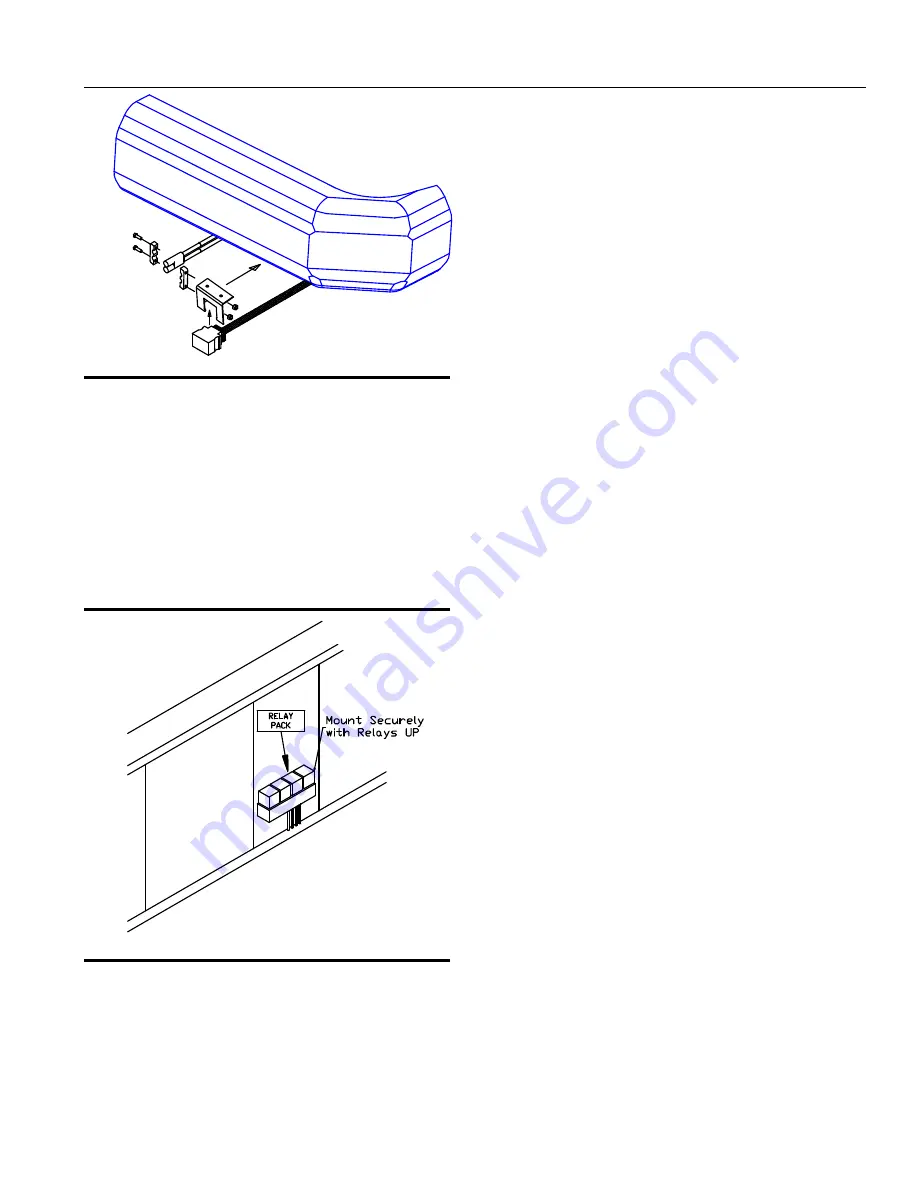
Figure 19.
Vehicle Connections
G10148
29. Mount the Black 15 Pin Control Harness
Connector to the lower area of the bumper using
MSC03813
Control Harness Mounting Bracket.
30. Mount the BLACK and RED 2 Pin Power Ground
Connector to the lower area of the bumper using
MSC03491
Power Ground Mounting Bracket.
Note:
Installation location will vary depending on
truck.
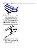
Figure 20.
Relay Mounting.
G10152
31. Attach the Relay Pack securely to the inside of the
engine compartment using four
HDW01766
Sheet
Metal Screws. The relays should be positioned
upright as illustrated above.
Содержание SMARTHITCH2 RT3 POWER-V
Страница 3: ...Snowplow Mounting Procedure 3 Figure 1 Mounting and Removal Instructions MSC04606 ...
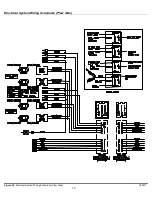
Страница 15: ...Electrical System Wiring Schematic Plow Side 15 Figure 24 Electrical System Wiring Schematic Plow Side G10271 ...
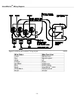
Страница 17: ...Electrical System Wiring Diagram 17 Figure 26 Electrical System Wiring Diagram G10134 ...


