Snowplow Assembly Procedure
5
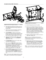
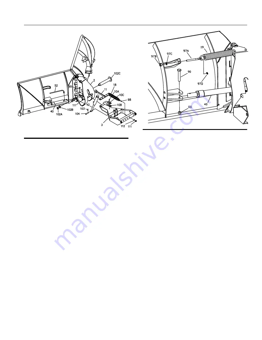
Figure 3.
Push Frame Assembly Procedure.
G10122
6. Stand Blade Assembly and Center Section (2) on
the Cutting Edges with both wings forward in the
scoop position.
7. Remove the loose Horizontal Hinge Pin (102C)
that is inserted in the Center Section (2).
8. Slide
TFR09708
Push Frame (3) into Center
Section (2). Re-insert Horizontal Hinge Pin (102C)
through Center Section (2) and Push Frame (3)
then secure with washer (102B) and nut (102A).
9. Attach Lift Cylinder (42) to Push Frame (3) with
HDW05563
Clevis Pin (104) and
HDW05544
Hairpin Cotter (103).
10. Hook
MSC04200
Spring Yoke (11) to the cross
rod inside Center Section (2).
11. Hook one end of
MSC01509
Trip Spring (18) to
Spring Yoke (11). Attach the opposite end of Trip
Spring (18) to the rear angle of Push Frame (3)
using HDW05601 Eyebolts (98), 5/8” Flat
Washers (112) and 5/8” Self-Locking Nuts (111) .
Tighten Self-Locking Nuts (111) finger tight.
12. Attach
HYD09731
Angle Cylinders (40) to Center
Section (2) using
HDW01706
5/8”-11 X 4” Hex
Head Cap Screws (90) and
HDW01709
5/8”-11
Self Locking Nuts (111). DO NOT over-tighten the
nuts.
Note:
You should be able to slightly slide the cylinder
up and down on the bolt after it has been tightened.
Figure 4.
Angle Cylinder Installation.
G10121
13. Pull both wings back into the ‘V’ position.
14. Hook one end of Return Spring (19) to the top
hole on Center Section (2). Hook the opposite end
of Return spring (19) to the blade spring mounting
bracket using ½” Spadebolt (97A), ½” Flat Washer
(97C), and ½” Self-Locking Nut (97B). Tighten
Spring (19) until there is a 1/32” space between
spring coils. Repeat this process for Return Spring
(19) on the opposite side of the plow.
15. Install one Push Nut Retainer (97D) on each end
of the Return Spring (19).
Note:
Be sure Push Nut Retainer’s flanges are
pointing away from the Eyebolt and toward the open
end of the Return Spring.
16. Bolt the rod end of Angle Cylinder (40) to each
blade half using 5/8”-11 X 4” Hex Head Bolt (90)
and 5/8”-11 Self Locking Nuts (111). DO NOT
over tighten bolts. Repeat this process for Angle
Cylinder (40) on the opposite side of the plow.
Note:
You should be able to slightly slide the cylinder
up and down on the bolt after it has been tightened.
Содержание SMARTHITCH2 RT3 POWER-V
Страница 3: ...Snowplow Mounting Procedure 3 Figure 1 Mounting and Removal Instructions MSC04606 ...
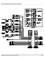
Страница 15: ...Electrical System Wiring Schematic Plow Side 15 Figure 24 Electrical System Wiring Schematic Plow Side G10271 ...
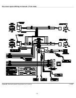
Страница 17: ...Electrical System Wiring Diagram 17 Figure 26 Electrical System Wiring Diagram G10134 ...


