80
Workshop Manual
Smart Tachograph EFAS-4.10/4.11
The EFAS test functions for the CAN bus (CAN A Test and CAN C Test) can support the determination of the correct termination.
CAN A
On delivery, EFAS is connected to CAN bus A, i.e. the terminating resistor is switched in. To remove the terminating resistor on
CAN bus A, use a suitable tool to remove the integrated fuse on the EFAS connector panel.
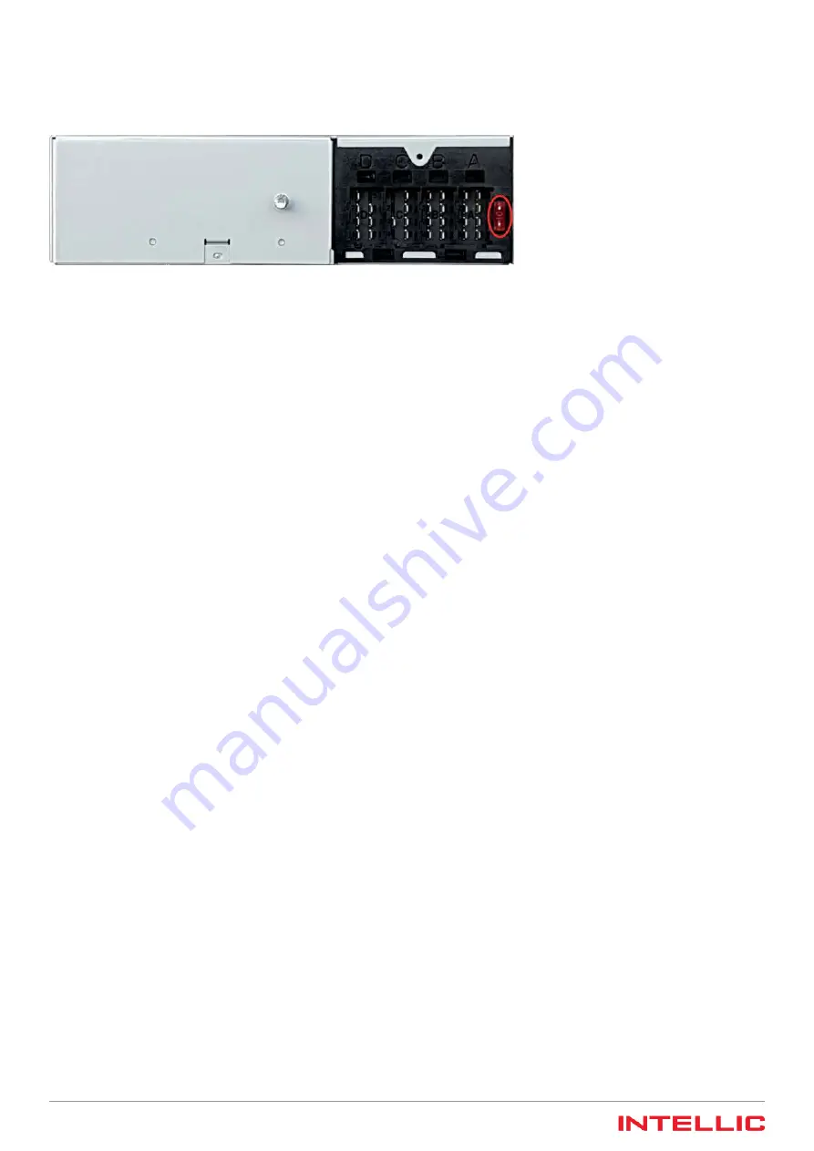
Figure 67 — Fuse that acts as terminating resistor on CAN bus A
If you wish to restore the terminating resistor for CAN bus A, replace the fuse you removed, or one identical to it, in the inte-
grated fuse holder on the EFAS connector panel. The fuse is a low profile MINI fuse. It acts as a low-resistance bridge only, and
so the nominal current value is unimportant.
CAN C
To connect the terminating resistor to CAN bus C, place a wire jumper between the connectors C7 and C8 on the C plug con-
nector. If a remote data download device is to be connected to CAN bus C, ensure that a jumper from C7 to C8 is inserted in the
red connector.
13.1.3
Data
For CAN bus data transfer in the automotive sector, transfer speeds are typically between 250 kbps and 500 kbps. Speeds of
250 kbps are typical for utility vehicles, while a speed of 500 kbps is often used for passenger cars, vans and pickup trucks.
The following data are transferred via the CAN bus main vehicle bus:
1. Data which the tachograph sends cyclically:
y
Vehicle speed
y
Engine speed (from the output shaft)
y
Tachograph status information
y
Mileage
y
Mileage per day
y
Driver and co-driver activities (“Resting” (
), “Standby” (
), “Working” (
), “Driving” (
))
y
Date, time and local time offset (according to time zone and daylight-saving adjustment)
y
Diagnostic status message (optional)
2. Data which the tachograph sends upon request:
y
Vehicle identification number (VIN)
y
Driver identification (DIN)
y
Service information
y
Diagnostics data
3. Data which the tachograph receives:
y
Lighting switch setting
y
Heartbeat from instrument panel / electronic tachometer
y
Reset command for daily mileage counter
y
Command to configure a local time offset
y
Engine speed
y
Gear ratio
y
Diagnostics queries
The data for speed, output shaft engine speed and driver activities is summarized in one message, the so-called “TCO1” message.
Data is transferred via the CAN bus in short message packets. Each message packet consists of a message ID and a number of
data bytes (generally 8 bytes). The ID indicates the data type and thus determines which bus subscriber the data is designated
for. Moreover, the priority and source of a message can also be defined via the ID. There is one essential distinctive feature, which
can cause IDs to differ from one another. This feature refers to the ID length, which is given in bits. IDs with a length of 11 bits
are generally used for vans and pickup trucks. However, HGVs with 24 V power supplies expect an ID with a length of 29 bits.
Содержание Intellic EFAS-4.10
Страница 1: ...Powered by Workshop Manual Smart Tachograph EFAS 4 10 4 11 ...
Страница 2: ......
Страница 4: ......
Страница 6: ......


