CB-100-1
50
5.1
Earth connection
EN 61800-5-1 (product standard for adjustable speed
electrical power drive systems) and
DIN EN 50178 DIN VDE 0160 (Electronic equipment
for use in power installations) have special earth re-
quirements as soon as an earth leakage current of
3.5 mA is exceeded.
• The protective earth conductor cross-section for the
line conductors (L1, L2, L3) < 16mm² must, in single
wire, be 10 mm
2
or must have two wires with the re-
spective phase cross-section each.
• For line conductors (L1, L2, L3) ≥ 16 mm² and ≤ 35
mm², the protective earth conductor must have a
cross section of 16 mm².
• For line conductors (L1, L2, L3) > 35 mm², the pro-
tective earth conductor cross-section must be at
least 50% of that of the phases used (L1, L2, L3).
All exposed metal parts in the VARIPACK frequency in-
verter are protected with a basic insulation and connec-
ted to the protective earth conductor.
WARNING
The VARIPACK frequency inverters can gener-
ate a direct current in the protective earth con-
ductor.
Risk of electric shock upon contact!
Wherever a residual current device (RCD) or a
residual current monitoring device (RCM) is
used for protection against direct or indirect con-
tact, only a RCD or RCM of type B (according to
IE/EN 60755) is permitted on the power supply
side!
Residual current circuit breakers (RCD or FI switch)
• Use only FI circuit breakers (RCD) sensitive to all
types of currents of type B that are capable of also
detecting residual direct currents.
• Select the RCD with respect to the system configura-
tion and environmental conditions.
5.2
Power connections (power cable and motor cable)
DANGER
Wrong or insufficient earthing may result in life-
threatening electric shocks upon contact with
the VARIPACK frequency inverter!
Earth the complete VARIPACK frequency in-
verter permanently and check the earth contacts
at regular intervals!
Prior to any intervention in the device, check all
voltage connections for proper insulation.
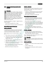
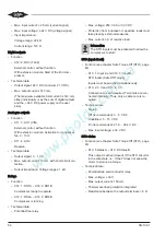
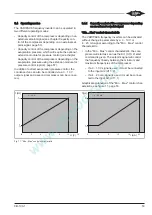
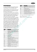
Graphical explanations, see figure 10, page 51.
• Guide power cable and motor cable through the in-
tended cable entries under the cable clips into the
VARIPACK frequency inverter (see figure 10, page
51) and connect to the power terminals. Observe
the tightening torques of the terminals (see table 3,
page 49).
– Connect the power cable to the terminals L1, L2,
L3 and the protective earth conductor.
– Connect the motor cable to the terminals U(M1),
V(M2), W(M3) and the protective earth conductor.
– Observe the information regarding electromag-
netic compatibility (EMC) (see chapter Electro-
magnetic compatibility (EMC), page 59)!
• As standard, the VARIPACK frequency inverters are
equipped with a shut-off function, the Safe Torque
Off (STO). Due to the STO function, the main con-
tactor before or after the VARIPACK frequency in-
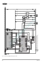
verter may be omitted (see chapter Schematic wiring
diagram, page 55). For further information on the
STO function, see chapter Safe Torque Off (STO),
page 60.
Содержание VARIPACK FDU+12
Страница 12: ...CB 100 1 12 1 2 3 4 Abb 7 Steuremodul abmontieren...
Страница 46: ...CB 100 1 46 1 2 3 4 Fig 7 Dismounting the control module...
Страница 64: ...CB 100 1 64 Fig 17 Graphical representation of the general control functions of the extension module...
Страница 70: ...Notes...
Страница 71: ...Notes...


