CB-100-1
40
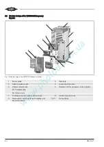
3.1
Modular design of the VARIPACK frequency
inverter
2
1
3
4
5
6
7
8
9
5a
10
11
5b
Fig. 1: Modular design of the VARIPACK frequency inverter
1
Power stack
2
Heat sink
3
Upper housing cover
4
Lower housing cover
5
Control module with
5a: Terminal strip
5b: SD card slot
6
Extension kit for pressure control (option)
7
Interface extension with real-time clock
8
Control module cover
9
Removable control panel (with display and
keypad) (option)
10+11
Fixing plates
Содержание VARIPACK FDU+12
Страница 12: ...CB 100 1 12 1 2 3 4 Abb 7 Steuremodul abmontieren...
Страница 46: ...CB 100 1 46 1 2 3 4 Fig 7 Dismounting the control module...
Страница 64: ...CB 100 1 64 Fig 17 Graphical representation of the general control functions of the extension module...
Страница 70: ...Notes...
Страница 71: ...Notes...


