CB-100-1
67
8
Commissioning of the VARIPACK frequency
inverter
Establish first:
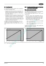
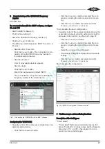
the communication with the BEST software, see figure
21, page 67:
• Start the BEST software (1).
• Click the N
EW
button (2).
• Select the VARIPACK frequency inverter (3).
• Click the C
ONNECT
button (4).
• The following selection appears: BEST C
ONVERTER
or
E
THERNET
.
– Selection B
EST
C
ONVERTER
:
Click the C
ONNECT
button. This concludes the con-
nection of the VARIPACK frequency inverter to
the mobile terminal device.
– Selection E
THERNET
:
A list of all available devices appears.
Select a device.
Click the C
ONNECT
button.
Enter Ethernet password (default "8670")
This concludes the connection of the VARIPACK
frequency inverter to the mobile device.
Fig. 21: Connecting the VARIPACK with the BEST software
Configuring the VARIPACK:
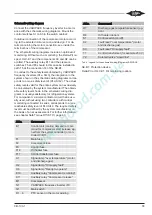
• Capacity control of the compressor depending on an
external setpoint signal:
– Click the C
ONFIGURATION
button.
– Click the C
OMPRESSOR
button and select the com-
pressor, including the motor code and motor wir-
ing.
– Click the T
RANSMIT
button and select and click
T
RANSMIT
USER
SETTINGS
TO
THE
DEVICE
.
This completes the basic configuration.
• Capacity control of the compressor depending on the
evaporation pressure using the extension module for
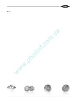
pressure control (option), see figure 22, page 67.
– Click the C
ONFIGURATION
button.
– Click the C
OMPRESSOR
button and select the com-
pressor, including the motor code and motor wir-
ing.
– Select the corresponding refrigerant.
– If necessary, adapt the temperature and pressure
settings.
– Click the T
RANSMIT
button and select and click
T
RANSMIT
USER
SETTINGS
TO
THE
DEVICE
.
This completes the configuration.
Fig. 22: VARIPACK configuration "Pressure control"
9
Fault messages and monitoring functions
Description of the fault types:
"Timed resets":
• "Timed reset" faults are automatically reset up to 5
times. If the fault is no longer active and the following
time delay of 10 s or 300 s has elapsed, the com-
pressor can be restarted again.
Содержание VARIPACK FDU+12
Страница 12: ...CB 100 1 12 1 2 3 4 Abb 7 Steuremodul abmontieren...
Страница 46: ...CB 100 1 46 1 2 3 4 Fig 7 Dismounting the control module...
Страница 64: ...CB 100 1 64 Fig 17 Graphical representation of the general control functions of the extension module...
Страница 70: ...Notes...
Страница 71: ...Notes...

