CB-100-1
42
4.3
Switch cabinet mounting
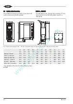
The VARIPACK frequency inverter is mounted in the
switch cabinet using the fixing plates.
FDU+6 .. FHU+73
The alternative bores, arranged at a spacing of 15 mm,
can be used to move the fixing plates upwards or
downwards.
B
B1
H
H2
F
L
B2
H1
B1
F
H3
X
B1
B3
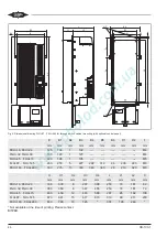
FKU+180 .. FKU+260
Fig. 3: Dimensional drawings FDU+6 .. FKU+260 for switch cabinet mounting (drawing shows FDU with optional control panel)
B
mm
B1
mm
B2
mm
B3
mm
F
mm
H
mm
H1
mm
H2
mm
H3
mm
L
mm
X
mm
FDU+6, FDU+12
100
80
10
---
M4
286
270
7
332
255
46
FEU+16, FEU+24
125
100
13
---
M4
333
320
7
398
255
62
FGU+32, FGU+38
150
125
13
---
M4
383
370
7
455
255
72
FHU+45 .. FHU+73
220
190
13
---
M5
480
465
7
588
287
108
FJU+87 .. FJU+145
260
220
20
---
M6
670
650
10
870
316
200
FKU+180 .. FKU+260
330
285
23
143
M8
800
780
10
*
374
*
* Not available at the time of printing. Please contact
BITZER.
Содержание VARIPACK FDU+12
Страница 12: ...CB 100 1 12 1 2 3 4 Abb 7 Steuremodul abmontieren...
Страница 46: ...CB 100 1 46 1 2 3 4 Fig 7 Dismounting the control module...
Страница 64: ...CB 100 1 64 Fig 17 Graphical representation of the general control functions of the extension module...
Страница 70: ...Notes...
Страница 71: ...Notes...

