CB-100-1
58
N
F3
L1
L2
L3
PE
L1
L2
L3
B2
S2
S1
01
S3
H1
H2
K11
Y2
F5
P>
F6
P<
K10 15
N
L
11
12
14
SE-B1
B1
B2
1
2
6
PE
g
rau
g
re
y/g
ris
br
aun
bro
wn
marron
violett
violet
violet
rosa
pink
rosé
b
lau
b
lue
b
leu
K10 15
*Individueller Anschluss je nach ge
wählter Motor
var
iante und A
uslegung.
*Individual connection depending on chosen motor v
ersion and design.
Details zum Anschluss siehe Innenseite des
V
erdichter-Anschlusskastens
.
Details concer
ning connections see inside the ter
minal bo
xof the compressor
.
R8
K10 15
Option
X12
1
2
3
4
5
6
X13
Delta-PII /
OLC-K1
or
ange
DI4
DI5/DO3
DI6 (IMB)
DO3 (FsC2)
P24V Output
0V
0V
DI1 (Start)
DI2 (Force)
DI3 (pe/po1->2)
P24V Input
0V Input
V
ARIP
A
CK
(N1)
X11
X10
AI1
AI2
AO1
AO2
P10V
N10V
Input A
0V
Input B
0V
Status A
Status B
Analog I/O
REF
Saf
ety circuit:
ST
O
U
(M1)
V
(M2)
W
(M3)
Dig.
Inputs
Output
Dig.
Inputs
Input
PW Y
∆
3
4
5
R7
(Option)
M1*
X14
2
1
DO2B
DO2A
DO1B
DO1A
RDY
2
1
VsC1
4
3
2
1
8
7
6
5
13
12
11
10
9
14
15
16
17
18
19
F1
Q1
1 0
20
1
2
3
4
5
6
1
2
3
4
5
6
1
2
3
4
5
6
F17
230V
T1
PE
L1
L3
H6
K10
20,21
22
R1..6
21
22
X3
X4
+24V in
+24V out
+24V out
+24V out
+24V out
+24V out
0V
0V
IMB (to FI)
FsC2 (to FI)
+24
V
DO
1
2
3
4
5
6
1
2
3
4
5
X2
out (to FI)
out (to FI)
0V
0V
0
V
1
2
3
4
A0
X1
0V
Signal
+5V Output
0V
Signal
+5V Output
1
2
3
4
5
6
X5
FsC2
1
2
p
grün, green, vert
schwarz, black, noir
e
p
c
p
e
p
c
p
e
p
c
F2
L2
F12
K11 19
K11 19
orange, orange, orange
violett, violet, violet
grau, grey, gris
weiß, white, blanc
braun, brown,
marron
rot, red, rouge
blau, blue, bleu
weiß, white, blanc
grün, green, vert
weiß, white, blanc
schwarz, black, noir
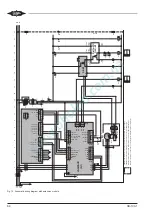
Fig. 14: Schematic wiring diagram with extension module
Содержание VARIPACK FDU+12
Страница 12: ...CB 100 1 12 1 2 3 4 Abb 7 Steuremodul abmontieren...
Страница 46: ...CB 100 1 46 1 2 3 4 Fig 7 Dismounting the control module...
Страница 64: ...CB 100 1 64 Fig 17 Graphical representation of the general control functions of the extension module...
Страница 70: ...Notes...
Страница 71: ...Notes...

