background image


VDL (E3.1) 06/2020 

Page 64/206 


Observe the permissible gas inlet temperature of the vacuum pump in use.

  Do NOT exceed this 

temperature. If the gas inlet temperature is too high and then becomes even warmer by compression in 
the pump, the resulting temperature (of the gas-solvent mixture inside the pump) could exceed the sol-
vent’s temperature class and auto-ignition temperature . 


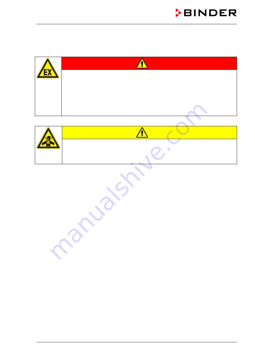
DANGER 

Fire and explosion hazard by exceeding the auto-ignition


temperature of the solvent 

with a too high gas inlet temperature. 

Damage to the vacuum pump. Serious injury or death from burns and / or explosion 
pressure. 

  Do NOT exceed the maximum gas inlet temperature of the pump. Adjust the tempera-

ture set-point accordingly. 

  With a higher set-point temperature, take appropriate measures to cool down the ex-

tracted vapor before it enters into the vacuum pump. 

Extracted vapors can have a health damaging and/or corrosive effect on the chamber and pump. 


CAUTION 

Health hazard due to release of extracted vapors. 

Corrosion


of oven and pump. Damage to health.


  Conduct the extracted vapors e.g., into a fume extractor facility. Connect a suitable 

hose to the vacuum pump outlet that may be located in the pump module. 

To avoid condensation inside the chamber and in the suction system, select an appropriate vacuum 
source to ensure its sufficient performance in relation to the released amount of steam. Coordinate drying 
temperature, suction performance of the vacuum source and the amount of loading material. 


Содержание vdl 115

Страница 1: ...0 0014 VDL 115 VDL115 230V 9630 0011 VDL 115 UL VDL115UL 120V 9630 0015 BINDER GmbH Address Post office box 102 78502 Tuttlingen Germany Phone 49 7462 2005 0 Fax 49 7462 2005 100 Internet http www binder world com E mail info binder world com Service Hotline 49 7462 2005 555 Service Fax 49 7462 2005 93 555 Service E Mail service binder world com Service Hotline USA 1 866 885 9794 or 1 631 224 4340...

Страница 2: ...fety instructions on the charging material 19 1 7 4 Safety instructions on operating the vacuum drying oven 20 1 8 Ex classification of the chamber and immediate surroundings 23 1 9 Intended use 25 1 10 Foreseeable Misuse 27 1 11 Residual Risks 29 2 OPERATOR RESPONSIBILITY DOCUMENTATION AND MEASURES 32 2 1 Risk assessment explosion protection document 32 2 2 Employee training and protocols 32 2 3 ...

Страница 3: ...p module option 66 6 5 4 Note on the use of a flame arrester 67 6 5 5 ATEX connection kit for vacuum pump VP4 option 68 6 6 Connecting inert gas supply 68 6 7 Mounting the tilt protection holders 69 6 8 Achieving equipotential bonding Grounding concept 70 6 9 Electrical connection 72 7 EXPLOSION SAFETY TESTS BEFORE COMMISSIONING 74 7 1 Scope of the functional test 74 7 2 Explosion protection plan ...

Страница 4: ...e pump 100 9 13 Preparing a new drying process 100 10 SET POINT ENTRY 101 10 1 1 Set point entry through the Setpoints menu 101 10 1 2 Direct setpoint entry via Normal display 102 11 SETTING SPECIAL CONTROLLER FUNCTIONS 103 11 1 Menu structure 103 11 1 1 Functions on off menu 103 11 1 2 Control on off menu 104 11 2 Using the optional universal connection GAS AIR 2 for ventilation 104 11 3 Close al...

Страница 5: ...ning timer program 136 17 3 Performance after the end of the program 136 18 TIME PROGRAMS 137 18 1 Starting an existing time program 137 18 1 1 Performance during program delay time 138 18 2 Stopping a running time program 138 18 2 1 Pausing a running time program 138 18 2 2 Cancelling a running time program 138 18 3 Performance after the end of the program 139 18 4 Creating a new time program 140...

Страница 6: ...mber 169 23 1 1 Checking the controller display 169 23 1 2 Checking the spatial temperature exactitude 169 24 OPTIONS 170 24 1 APT COM 4 Multi Management software option 170 24 2 Analog outputs for temperature and pressure option 170 24 3 Measuring access port for vacuum 9 poles option 170 24 4 Object temperature display with flexible Pt 100 temperature sensor option 171 24 4 1 Connection of the o...

Страница 7: ...ification in the surroundings of the chamber schematic representation 48 Figure 9 Area classification in the surroundings of the chamber during operation example 49 Figure 10 Operating the expansion racks 56 Figure 11 Mounting the pressure regulator on the chamber rear 57 Figure 12 Compressed air connection on the pressure regulator 59 Figure 13 VDL mounted on pump module 60 Figure 14 Pump module ...

Страница 8: ...e and familiar with all precautionary measures required for working acc to ATEX Directive 2014 37 EU Observe the national regulations on minimum age of laboratory personnel 1 2 Operating manual This operating manual is part of the components of delivery Always keep it handy for reference in the vicinity of the chamber If selling the unit hand over the operating manual to the purchaser To avoid inj...

Страница 9: ...rranty administration and the general terms and conditions as well as the legal regulations valid at the time the contract is concluded The statements in this manual neither aug ment nor restrict the contractual warranty provisions Furthermore relevant national and international regulations on occupational safety apply The operator must know comply with and implement these requirements In particul...

Страница 10: ...ly hazardous situation which if not avoided could result in death or serious irre versible injury CAUTION Indicates a potentially hazardous situation which if not avoided may result in moderate or minor re versible injury NOTICE Indicates a potentially hazardous situation which if not avoided may result in damage to the product and or its functions or to property in its proximity 1 4 2 Safety aler...

Страница 11: ...ution Hazard Mandatory action signs Mandatory regulation Read operating instructions Disconnect the power plug Lift with several persons Environment protection Wear protective gloves Wear eye protectors Ground before use Release before mainte nance or repairs Wear ESD shoes antistatic shoes Wipe with damp cloth only Prohibition signs Do NOT touch Do NOT spray with water Do not place anything on th...

Страница 12: ...ons that could result in direct or indirect injury or property damage 1 5 Localization position of safety labels on the chamber The following labels are located on the chamber door Safety labels Hot surface Observe sweeping time read operating manual Do not place anything on the chamber Service label Wipe surfaces with damp cloth only Figure 1 Position of labels on the chamber example Keep safety ...

Страница 13: ... Explosion proof inner chamber Ex classification acc to 2014 34 EU Ex II 2 3 G IIB T3 Gb Gc X Ex classification according to ATEX Directive 2014 34 EU Max temp of inner chamber surface in cat 2 160 C Maximum temperature of the inner chamber surfaces 160 C 320 F Device category 2 Max temp of heating surface in cat 3 185 C Maximum temperature of the surfaces at the heater 185 C 365 F Device category...

Страница 14: ...tional measures for explosion protection determined and specified on the basis of the risk as sessment In accordance with ATEX Operational Directive 1999 92 EC these measures serve to prevent the formation of or to limit explosive atmospheres or to limit hazardous explosive mixtures to avoid the combustion of explosive atmospheres to limit the spread of an explosion and to minimize its effects on ...

Страница 15: ...losion that cannot be ex cluded particularly in relation to the environment of the chamber To minimize this risk strictly observe the legal regulations about how to select an appropriate location Do not install and operate the vacuum drying oven VDL in occasionally or continuously for long periods frequently potentially explosive areas DANGER Explosion hazard due to combustible dusts or explosive ...

Страница 16: ... connection must therefore be established out side a zone 1 7 1 5 Technical ventilation extraction The operator shall provide active extraction technical ventilation according to country specific regulations TRBS 2152 Part 2 for Germany before commissioning the chamber Extraction must include the entire installation area of the vacuum drying oven and a vacuum pump Observe the area classification i...

Страница 17: ...oof pumps See chap 6 5 1 Operate the pump in a stationary position and secure it so it is immobile Make sure that the suction line to the vacuum connection 6 of the VDL is fixed and conductive Ensure sufficient solvent condensation e g in an exhaust waste vapor condenser to avoid that ignitable solvent concentrations are conducted from the pump Otherwise the exhaust pipe after the pump must be fix...

Страница 18: ... pump removing the filled condensate catchpot of the pump or in the event of an error e g dropping or spilling the filled condensate catchpot spreading of an explosive at mosphere to unprotected parts of the pump or the vacuum drying oven would be possible The operator must provide active extraction technical ventilation according to country specific regulations TRBS 2152 Part 2 for Germany prior ...

Страница 19: ...le dusts into the chamber Do NOT introduce any substance which tends towards exothermal decomposition into the chamber Do NOT introduce any substance which comes under the explosive substance law into the chamber Do NOT introduce energy sources such as batteries or lithium ion batteries into the chamber Do NOT introduce any substance which could lead to release of toxic gases into the chamber Fami...

Страница 20: ...technical ventilation in the area of the vacuum pump stand particularly in the areas of the condensate catchpot when emptying it and the exhaust air of the vacuum pump The personal protective equipment PPE of the operating personnel must be ESD pro tected Only trained personnel with password authorization may work on the VDL vacuum drying oven DANGER Electrical hazard by water entering the chamber...

Страница 21: ...res are active Respect the relevant regulations for handling inert gases When decommissioning the vacuum drying oven shut off the inert gas supply If solvent containing air penetrates the electrical area of the oven explosions may result DANGER Explosion hazard by solvent containing air penetrating the electrical area of the oven Serious injury or death from burns and or explosion pressure Do NOT ...

Страница 22: ...ed Make sure that the technical ventilation is active Introduce the drying material Start the drying process The heating unit is only released when a pressure threshold of 100 mbar is reached Make sure that sweeping the area for electrical equipment and controller housing with at least 25 Pa overpressure see manometer display takes place during the entire operating cycle Recommended value 40 Pa Th...

Страница 23: ...area The device power plug is unprotected The electrical connection must therefore be established outside a zone See images of the areas in Chap 3 5 G Device category G per ATEX Directive 2014 34 EU Gas Do not introduce combustible dust into the chamber or allow combustible dusts to be pre sent in the vicinity of the chamber IIB Equipment group IIB Substances falling under Gas group Explosion grou...

Страница 24: ...s reset by disconnecting and reconnecting the power plug No classification The expansion vessel is located in the area of the heating piping zone 2 possible It is a purely me chanical component with no risk of ignition The relay and self holding circuit are located in the overpressure swept electrical installation area Pt 100 controller sensor and heating sensor Both sensors are located on the hea...

Страница 25: ...t lie below the sublimation point of the loading material The VDL vacuum drying ovens are approved for drying of materials with organic solvents This may cause unlimited amounts of solvents to appear temporarily The chambers are equipped with an explo sion proof inner chamber The VDL vacuum drying ovens are not intended for installation in a Zone 1 or 0 The chamber must not be installed or operate...

Страница 26: ...on with explosive dust atmospheres or hybrid mixtures Combustible dust are generally not permitted DANGER Explosion or implosion hazard and danger of poisoning by introduction of unsuita ble loading material Serious injury or death from burns and or explosion pressure or by poisoning Do NOT introduce any substance with an auto ignition temperature below 200 C 392 F into the chamber Do NOT introduc...

Страница 27: ...conditions Chap 5 must be met In case of foreseeable use of the chamber there is no risk for the user through the integration of the chamber into systems or by special environmental or operating conditions in the sense of EN 61010 1 2010 For this the intended use of the chamber and all its connections must be observed 1 10 Foreseeable Misuse Other applications than those described in chap 1 8 are ...

Страница 28: ...nstallation startup operation maintenance or repair of the chamber in absence of a risk assessment and operating instructions from the operator Deliberate or careless handling of the chamber during operation except the permitted operation of the controller Bypassing or changing protective systems operation of the chamber without the designated protective systems Establishing or disconnecting an el...

Страница 29: ...inserting or remov ing the expansion racks Explosion hazard due to mechanical formation in an explosive atmos phere due to rust Serious injury or death from burns and or explo sion pressure Observe the warnings in the operating instruc tions and follow the instructions for checking the chamber and expansion racks for corrosion Do not use corroded components Never allow rust to permeate into the ch...

Страница 30: ... surfaces on the housing Contact with hot surfaces in the interior and inside of doors Emission of non ionizing radiation from electrical operating resources Use of inert gas in higher concentration optional Use of unsuitable pump and discharge Excessively high gas intake temperature or insufficient cooling of the extracted vapor before entering the vacuum pump Contact with live parts in normal st...

Страница 31: ...e Manual Trouble shooting of live parts without specified safety measures Absence of a plausibility check to rule out erroneous inscription of electrical components Performance of repair work by untrained insufficiently qualified personnel Inappropriate repairs which do not meet the quality standard specified by BINDER Use of replacement parts other than BINDER original replacement parts Electrica...

Страница 32: ...ion and evaluation of explosion hazards Explosion protection plan The explosion protection plan to be created by the operator represents the entirety of the technical and organizational measures for explosion protection determined and specified on the basis of the risk assessment These measures should prevent the formation of hazardous explosive mixtures or to limit or prevent their ignition They ...

Страница 33: ... more operating instructions These must comply with regulatory requirements and be verified regularly to ensure that they are up to date When creating the operating instructions follow applicable national regulations for Germany Industrial Safety Regulation BetrSichV Ordinance on Hazardous Substances GefStoffV Keep these operating instructions with the chamber at all times in a place where they ar...

Страница 34: ...s takes place in a vacuum There is only a risk in the event of prema ture air supply termination of the drying process Avoid premature air supply Also observe the instructions in the Operating Manual Reloading with the a material with a lower auto ignition tem perature Prior to each new drying procedure check again the auto ignition temperature with the safety specifications and the desired drying...

Страница 35: ...airs in a system book For testing before commissioning see Chap 7 For recurring tests and maintenance see Chap 7 5 7 6 25 2 8 Operation log For safety reasons keeping an operation log which documents each individual drying process is recom mended The following contents should be entered and recorded Type of solvent Auto ignition temperature of the solvent in the case of solvent mixtures solvent wi...

Страница 36: ...g oven Serial number Solvent In the case of solvent mixtures solvent with the lowest Auto ignition temperature Auto ignition temperature unit Drying tem perature temperature set point unit Safety controller mode Limit Offset Safety control ler value unit Date Signature ...

Страница 37: ...onnection must be established outside a zone Temperature class The temperature class of the inner chamber acc to EN 60079 0 is T3 The temperature class of the entire chamber equals the temperature class of the inner chamber Controller The chambers are equipped with a multifunctional microprocessor display controller with 2 channel tech nology for temperature and pressure Temperature is indicated a...

Страница 38: ...ying oven 3 1 Manufacturer s safety plan Protective measures and equipment The following measures were taken on the manufacturer s side in order to prevent ignition and explo sions Ignition source monitored via safety temperature limiter TL class 2 Only solvents with an auto ignition temperature above 200 C may be entered into the chamber There is a safety margin of 20 of the minimum permissible a...

Страница 39: ...oller housing are protected against penetration of ex plosive atmosphere by a technical ventilation system minimum overpressure 25 Pa The user must monitor the pressure on the manometer on the chamber front especially when loading and removing the loading material This reliably prevents explosive atmosphere to reach electrical or electronic parts of the VDL safety vacuum drying oven protection aga...

Страница 40: ...the operator can manually turn off the chamber immediately pull the power plug or operate e g a customer s explosion protected emergency stop switch in order to pre vent the chamber from restarting automatically If during a fault of the technical ventilation caused by a power failure material containing a solvent is located in the loading area of the chamber the operator must ensure that after the...

Страница 41: ...splay which can be read from outside The safety measuring and control equipment is easily accessible Non ionizing radiation Non ionizing radiation is not intentionally produced but released only for technical reasons by electri cal equipment e g electric motors power cables solenoids The machine has no permanent mag nets If persons with active implants e g pacemakers defibrillators keep a safe dis...

Страница 42: ...ng manual chap 5 for correct installation Cleaning See operating manual chap 25 Maintenance For maintenance instructions for the user please refer to operating manual chap 26 Detailed instructions are included in the service manual for this chamber ...

Страница 43: ... Chamber overview Figure 3 VDL 115 with MB2 controller A Area for electrical equipment B Triangular instrument box controller housing with chamber controller C Chamber door D Door handle E Elastic mounted safety glass window A B C D E ...

Страница 44: ...interface Pilot lamp Figure 4 Triangular instrument box controller housing with MB2 program controller and USB interface 3 4 Connections on the rear of the chamber Rear connection panel Mounting holes for fixing the tilt protection holders 12 Measuring connection with small flange DN16 Figure 5 Chamber rear example VDL 115 ...

Страница 45: ...VDL E3 1 06 2020 Page 45 206 1 2 3 5 8 9 VDL 23 6 4 7 10 1 2 3 5 8 9 VDL 56 4 6 7 10 1 2 3 5 8 9 VDL 115 4 6 7 10 Figure 6 Rear connection panel VDL with options ...

Страница 46: ...r with hose olive 8 mm 0 31 in 6 Vacuum connection with small flange DN16 7 Plug Manual ventilation for emergency ventilation in case of power failure 8 Heatsink 9 Pressure regulator for sweeping overpressure 10 Compressed air connection for sweeping overpressure 3 5 Area classification information for the zone classification The operator is to classify the zones The following areas are identified...

Страница 47: ...al installation area swept with compressed air H Inner chamber usable volume 7 Plug Manual ventilation for emergency ventilation 4 Universal connection for inert gas ambient air GAS AIR 5 Additional universal connection for inert gas ambient air GAS AIR 2 option 6 Vacuum connection 12 Measuring connection Occurrence of an explosive atmosphere occasionally Inner chamber with tubing line to the vacu...

Страница 48: ...l connection must be established outside a zone Spreading of an explosive atmosphere which may occur on a rare and temporary basis to unprotected areas must be reliably prevented by measures of the operator In particular this includes a sufficiently dimensioned one technical ventilation according to country specific regulations TRBS 2152 Part 2 for Germany Figure 8 Area classification in the surro...

Страница 49: ... VDL Pump module with pump example front rear Pump example VDL rear Figure 9 Area classification in the surroundings of the chamber during operation example Occurrence of an explosive atmosphere occasionally interior of VDL line to the vacuum pump pump on a rare and temporary basis surroundings of VDL and pump interior of the pump module ...

Страница 50: ...his thor oughly reinstall the plug CAUTION Risk of injury due to sliding or tilting of the chamber in case of improper lifting Injuries damage to the chamber Do NOT lift the chamber using the door or the handle Do NOT use technical equipment to lift the chambers Lift chambers size 23 and 56 from the pallet at the four lower corners with the aid of 4 people Lift chambers size 115 from the pallet wi...

Страница 51: ...elines for temporary decommissioning chap 27 2 Permissible ambient temperature range during storage 10 C 14 F to 60 C 140 F Permissible ambient humidity max 70 r h non condensing When after storage in a cold location you transfer the chamber to its warmer installation site condensa tion may form Before start up wait at least one hour until the chamber has attained ambient temperature and is comple...

Страница 52: ...ER Explosion hazard by penetration of an explosive atmosphere to unprotected areas Serious injury or death from burns and or explosion pressure Do NOT operate the chamber in in occasionally or continuously for long periods fre quently potentially explosive areas It is not intended for installation in a zone 1 or 0 Make sure that there are NO combustible dusts in the vicinity of the chamber Make su...

Страница 53: ... ventilation 5 2 1 Ventilation for heat removal in normal operation Install the vacuum drying oven in a well ventilated place NOTICE Danger of overheating due to lack of ventilation Damage to the chamber Do NOT set up chambers in non ventilated recesses Ensure sufficient ventilation for dispersal of the heat Observe the prescribed minimum distances when installing the chamber chap 5 1 5 2 2 Techni...

Страница 54: ... surface of the chamber must be electrically conductive This installa tion and operating surface must be connected to the vacuum drying oven and other equipment e g Pump module vacuum pump according to the grounding concept Provide cyclic measurements For the grounding concept see chap 6 8 When inserting or loading objects into the loading area note that there may be a potential equalization The p...

Страница 55: ... 6 1 Vacuum expansion racks and rack holders Vacuum expansion racks and rack holders can easily be removed from the chamber This offers the advantage of an inner chamber with smooth walls which is easy to clean Inserting or loosening an expansion rack and inserting or removing the rack holders may only be done in the absence of solvents and under extraction technical ventilation The rack holders c...

Страница 56: ...sed and can be removed Pulling the locking lever The expansion rack is pressed against the inner chamber walls Remove or insert the vacuum expansion racks only when the chamber is empty and has cooled down NO explosive atmosphere must be present Active extraction technical ventila tion is mandatory Following each new tightening of an expansion rack check that the lateral parts of the rack fit clos...

Страница 57: ...g the pressure regulator a pressure regulator b tube c 6 screws d brass nozzle for compressed air connection e bracket f cable connector g 2 nuts for the bolts with thread on the chamber rear Connections on the chamber rear as supplied h hole for the cable connection i 2 bolts with thread Figure 11 Mounting the pressure regulator on the chamber rear g a b d c h i i f c e d b a g f e ...

Страница 58: ...together with the bracket l e on the pressure regulator Fixation on the chamber rear Guide the tube b through the cable connector f and push the bracket e with the pressure regulator with its lower two holes onto the two bolts i on the rear of the chamber Screw the two nuts g onto the bolts i and tighten them Tighten the nut of the cable connector f which points to the chamber clockwise with a too...

Страница 59: ...egulator If solvent containing air penetrates the electrical area of the chamber explosions may result DANGER Explosion hazard by solvent containing air penetrating the electrical area of the chamber Serious injury or death from burns and or explosion pressure Make sure that the air for the compressed air supply is NOT taken from explosive at mospheres Do NOT start the VDL vacuum drying oven when ...

Страница 60: ...decommissioning the vacuum drying oven shut off the inert gas supply Close valve 6 6 4 Pump module option The mounting instructions Art no 7001 0137 supplied with the pump moduledescribe how to mount the vacuum drying oven onto the pump module and installing the suction line into the pump module Figure 13 VDL mounted on pump module example size 115 Figure 14 Pump module rear view example size 115 ...

Страница 61: ...le is supplied which is already fixed at the pump module It will be connected to the pump To establish a conductive connection between the condensate collecting tray and the pump module the front edge of the tray is screwed on the front of the vacuum module To establish a conductive connection between the pump module and the conductive surface of the installation site a grounding cable is supplied...

Страница 62: ...n according to country specific regulations TRBS 2152 Part 2 for Germany prior to commissioning the chamber Extraction must include the entire installation area of the vacuum drying oven and pump module Connect an extraction system to the provided port on the rear of the pump module 6 5 Vacuum connection Connect the vacuum drying oven to a vacuum pumpor to a domestic vacuum system For this purpose...

Страница 63: ... or death from burns and or explosion pressure Use only suitable explosion proof pumps Operate the pump in a stationary position and secure it so it is immobile Make sure that the suction line to the vacuum connection 6 is installed fix and conduc tive Avoid that the exhaust pipe conducts ignitable solvent concentrations by sufficient sol vent condensation e g in an exhaust waste vapor condenser M...

Страница 64: ...ature of the pump Adjust the tempera ture set point accordingly With a higher set point temperature take appropriate measures to cool down the ex tracted vapor before it enters into the vacuum pump Extracted vapors can have a health damaging and or corrosive effect on the chamber and pump CAUTION Health hazard due to release of extracted vapors Corrosion of oven and pump Damage to health Conduct t...

Страница 65: ...thout any zone sweeping with inert gas is not required In addition to sweeping with inert gas in case of condensing me dia you can connect a gas ballast in order to avoid condensation The ATEX Directive 2014 34 EU compliant vacuum pump offered by BINDER is designed for a gas inlet temperature of 40 C 104 F max Do NOT exceed this temperature If the gas inlet temperature is too high and then becomes...

Страница 66: ...ideration of any possible residual solvent contents The operator must check if an explosive atmos phere may be present at the pump exit or at the exhaust waste vapor condenser For this purpose use a calculation of the solvent s partial pressure at the set up coolant temperature of the exhaust waste vapor condenser and compare it to the explosion limits of the pumped solvent The exhaust sol vent co...

Страница 67: ... entry into the vacuum source The ATEX Directive 2014 34 EU compliant vacuum pump offered by BINDER is designed for a gas inlet temperature of 40 C 104 F max Do NOT exceed this temperature If the gas inlet temperature is too high and then becomes even warmer by compression in the pump the resulting temperature of the gas solvent mixture inside the pump could exceed the solvent s temperature class ...

Страница 68: ...n of inert gases can cause drowsiness up to respiratory arrest When the O2 content of the air decreases below 18 there is risk of death from lack of oxygen Any gas that might escape has to be led out via good room ventilation or a suitable exhaust system DANGER Risk of suffocation by inert gas in a high concentration Death by suffocation Do NOT set up chambers in non ventilated recesses Ensure tha...

Страница 69: ...bend the tilt protection holders accordingly Figure 17 Variable length of the tilt protection holder depending on the bend Installation on the chamber Plug the two tilt protection holders each with the tab into the mounting holes and push them upward over the rear panel The screw holes in the rear wall and in the tilt protection holders must align Fix the tilt protection holders each with one of t...

Страница 70: ...nnected to the conductive surface or to each other according to the grounding concept The personal protective equipment PPE of the operating personnel must be implemented ESD protect ed Installation without pump module Installation with pump module Figure 18 Possibilities of grounding schematic representation VDL Vacuum drying oven M Pump module S Walkable installation and operating surface with c...

Страница 71: ...ng we recommend performing a protective conductor measurement before commissioning The VDL provides a threaded bushing for grounding on the bottom left of the rear panel In state of delivery the screw together with the washer and spring washer is screwed on the threaded bushing Unscrew the screw Threaded bushing after unscrewing Washer spring washer screw Put the washer the ring cable lug of the g...

Страница 72: ...le of at least 2000 mm 78 74 in in length and a shockproof plug Model Power plug of the power cable Nominal voltage 10 at the indicated power frequency Current type Chamber fuse VDL 23 Grounded plug 230 V at 50 Hz 230 V at 60 Hz 1N 2 x 6 3 A VDL 56 Grounded plug 230 V at 50 Hz 230 V at 60 Hz 1N 2 x 8 A VDL 115 Grounded plug 230 V at 50 Hz 230 V at 60 Hz 1N 2 x 10 A VDL 23 UL NEMA 5 15P 100 120 V a...

Страница 73: ...able is damaged Pollution degree acc to IEC 61010 1 2 Over voltage category acc to IEC 61010 1 II See also electrical data chap 28 3 To completely separate the chamber from the power supply you must disconnect the power plug Install the chamber in a way that the power plug is easily accessible and can be easily pulled in case of danger A customer s emergency stop switch or a comparable power disco...

Страница 74: ...oring body or by personnel qualified for testing Observe relevant regulations for the qualification requirement Devices protective systems safety control and regulating devices according to Directive 2014 34 EU connection devices and interactions with other parts of the system must continue to be checked at least every three years Tests of ventilation systems gas warning and inerting devices must ...

Страница 75: ...es to deter mine the explosion safety of the system including the work equipment and the working environment The test represents a comprehensive consideration of the explosion safety of the Ex system with regard to the protection of employees and other persons in the hazard area including all functional units relevant to explosion protection and their interactions The test of explosion safety is b...

Страница 76: ...ing so assess whether the system can be operated safely until the next specified recurring test 7 4 1 4 Verifying the maintenance plan When doing so assess whether the maintenance plan is suitable for maintaining the safety of the Ex system until the next recurring test The maintenance plan can also be used to test the technical protec tive measures for explosion protection of the explosive system...

Страница 77: ...rvice manual customer version Ex devices in the sense of TRGS 725 whether they ensure the necessary functional reliability of the measures Connection elements and other technical devices such as lightning protection requirements for floors with regard to their condition their interconnections and their installation assembly for explo sion safety e g type of installation insulation resistance of el...

Страница 78: ...programming week and time programs In addition there is a timer program available stopwatch function The controller offers various notifications and alarm messages with visual and audible indication and re mote alarms via e mail an event list trace file and the graphical display of the measuring values in the in der chart recorder view The MB2 program controller permits programming temperature and...

Страница 79: ...ion icons Date time authorization level of the logged in user memory Quick setpoint entry Continue to next screen Back to Normal display Information Program start Setpoint entry Event list Display of active alarms Access to main menu Figure 21 Operating functions of the MB2 controller in normal display example values ...

Страница 80: ...e Change view icon to toggle between normal display program display and chart recorder display Press the Normal display icon to return from program display and chart recorder display back to Normal display Normal display actual values setpoint values Program display example time program Chart recorder display ...

Страница 81: ... or week program Information Information on program operation setpoints actual values and the safety controller Normal display Return from program display or chart recorder display to Normal display Change view Toggle between Normal display program display and chart recorder display Functional icons in individual menus Icon Signification Function Back Return from each menu to Normal display Update...

Страница 82: ... the history display to scroll to an instant Hide scroll buttons Hide scroll buttons in the history display to scroll to an instant Information icons referring to chamber conditions Icon Text information Condition Standby Chamber is in Standby mode Heating active Chamber is heating up All valves are closed All valves are closed GAS AIR Ventilation via regular connection GAS AIR 4 GAS AIR 2 Ventila...

Страница 83: ...00 switching points each The switching points can be distributed over all days of the week 8 4 1 MB2 controller menu structure Use the navigation icons in the screen footer in Normal display to access the desired controller func tions The available functions depend on the current au thorization level Service Admin or User chap 12 1 This is selected either during login or can be available without p...

Страница 84: ...ot visible for user with User authorization level chap 13 Programs submenu not visible for user with User authorization level chap 18 und 19 Service submenu chap 8 4 4 BINDER Service contact page chap 13 6 Calibrating the touch screen chap 13 4 2 Back to Normal Display Settings submenu Settings of many general controller functions and network settings chap 13 Available only for users with Service ...

Страница 85: ...imum and maximum val ues chap 22 2 Setting the tolerance range and delay time for tolerance range alarm chap 15 not used Entry of the MAC address and IP address chap 20 1 Password protection for web server access chap 20 2 Configuration of the e mail server assignment of e mail addresses chap 20 3 Back to main menu 8 4 4 Service submenu The Service submenu is available for users with Service or Ad...

Страница 86: ... Selection menu example Entry menu example After completing the settings there are the following possibilities Press the Confirm icon to take over the entries and exit the menu or continue the menu se quence Press the Close icon to exit the menu or cancel the menu sequence without taking over the en tries When terminating a menu sequence an information window appears which must be confirmed ...

Страница 87: ...d pressure threshold of 100 mbar the heater turns on depending on the setpoint After the power returns the controller continues to function in the original operating mode it was in pre viously before the power failure occurred Performance after power failure in Fixed value operation mode All functions return to the same status the chamber had before power failure The set points are im mediately re...

Страница 88: ...re for one day and in a well ventilated location Do not start up the chamber without technical ventilation chap 5 2 2 9 1 Requirements for safe commissioning Prior to turning on the chamber the following points must certainly be met Installation of the chamber chap 6 performed in compliance with the installation guidelines and am bient conditions chap 5 Connection for compressed air or inert gas f...

Страница 89: ...chamber front Sweeping before starting up the chamber Open the USB cover on the controller housing triangle instrument box Turn the pressure regulator until the end stop to the lock nuts turn clockwise Recommended time for sweeping with maximum overpressure 10 minutes This flushes 5 times the volume of the electrical installation area and controller housing Close the USB cover on the controller ho...

Страница 90: ...at maximum overpressure with compressed air or inert gas for at least 10 minutes Close the USB cover on the controller housing and adjust the pressure regulator by checking the manometer so that there is at least 25 Pa overpressure recommendation 40 Pa Loading and starting the drying process Make sure that the technical ventilation is activated Make sure that equipotential bonding has been establi...

Страница 91: ...ressed air or inert gas supply For emptying the pump Make sure that the pump is turned off Make sure that the technical ventilation is activated Make sure that equipotential bonding has been established according to the grounding con cept Make sure that the user s equipment is ESD protected Remove the full condensate catchpot of the pump Before starting a new drying process In case of a new solven...

Страница 92: ...e with an overpressure of at least 25 Pa recommendation 40 Pa during the entire operation of the vacuum drying oven Also after termination or cancellation of the drying process continued sweeping for at least 10 minutes is rec ommended DANGER Explosion hazard by solvent containing air penetrating and concentration in the electrical area of the chamber Serious injury or death from burns and or expl...

Страница 93: ...hes or falls below the required pressure threshold of 100 mbar the heater turns on depending on the setpoint 9 6 Standby mode Turning on and off the vacuum drying oven Before turning on the chamber the following points must surely be met Equipotential bonding established Chap 6 8 Technical ventilation is activated 10 minutes sweeping the area for electrical equipment and the controller housing Act...

Страница 94: ... to activate it for 10 sec onds Deactivating the Standby mode turning on the chamber To deactivate the Standby function unmark the checkbox 9 7 Controller settings upon start up Depending on the functions activated in the controller various settings can be requested directly after turning on the chamber Then you should assign a password for the operating level chap 12 The window Language selection...

Страница 95: ... no lock icon in the header 9 8 Loading Without technical ventilation the chamber must not be loaded with material containing sol vents The chamber cannot be loaded when turned off in standby mode Before loading the material to be loaded note When loading the chamber also in the context of intended use an explosive mixture may form in the working space Therefore a safety area of at least 1 m in fr...

Страница 96: ...uld lead to release of toxic gases into the chamber If the auto ignition temperature of a solvent contained in the drying material is exceeded during the drying process there is an immediate risk of fire and explosion Make sure that the auto ignition temperature of a solvent contained will NEVER be reached DANGER Fire and explosion hazard when exceeding the auto ignition temperature of the sol ven...

Страница 97: ...the controller When the decreasing pressure reaches the set point value the drying process is completed If the drying moni toring chap 11 6 is activated a corresponding message is displayed To break the vacuum ventilation after completing the drying procedure set the desired pressure set point to atmospheric pressure chap 10 The ventilation valve opens and ambient air or inert gas flow into the in...

Страница 98: ...tting in order to avoid perturbation inside the oven and release of big quantities of inert gas after flooding the VDL Following evacuation an inert gas e g nitrogen is led into the inner chamber via the connection GAS AIR 4 or the optional connection GAS AIR 2 5 until pressure compensation with the atmos phere occurs Depending on the individual application you can perform a second evacuation and ...

Страница 99: ...erature has sunk to ambient temperature Prior to a termination of a not completed drying process make sure that the auto ignition tem peratureof the solvent has been determined correctly and that the drying temperature reached far below this In case of doubt do not interrupt the drying process Proceeding to terminate the drying process Set the temperature set point to approx ambient temperature th...

Страница 100: ...tial bonding The accessible installation and operation area of the equipment must be conductive This area and the vacuum pump must be connected with the vacuum drying oven according to the grounding plan Chap 6 8 Activate the technical ventilation extraction The operator shall provide active extraction technical ventilation according to country specific regula tions TRBS 2152 Part 2 for Germany pr...

Страница 101: ...perature with the safety specifications of the solvent In the case of solvent mixtures use the au to ignition temperature of the material with the lowest auto ignition temperature In Fixed value operating mode you can enter a temperature set point a pressure set point and the switching state of special controller functions All settings made in Fixed value operating mode remain valid until the next...

Страница 102: ...t type Limit adapt the safety controller chap 14 2 always when you changed the temperature set point Set the safety controller set point by approx 5 C above the con troller temperature set point Recommended setting Set point type Limit with safety controller set point 5 C As long as the pressure threshold of 100 mbar has not yet been reached the icon Pressure threshold not reached in the screen he...

Страница 103: ...tion Settings for program oper ation are described in chap 18 7 3 time programs and chap 19 6 5 week programs In the Functions on off menu you can define the switching state of three controller functions Press the Setpoint setting icon to access the Setpoint setting menu from Normal display Path Setpoint Fixed value operation setpoints Functions on off Function Standby chap 9 6 Function GAS AIR 2 ...

Страница 104: ...activate the desired function and press the Confirm icon 11 2 Using the optional universal connection GAS AIR 2 for ventilation Regularly the universal connection for inert gas ambient air GAS AIR 4 is used for ventilation The GAS AIR 2 function serves to close the valve of the standard connection GAS AIR 4 and acti vate the valve of the optional universal connection GAS AIR 2 5 which is then used...

Страница 105: ... responding text information GAS AIR 2 information messages chap 16 1 11 3 Close all valves Close all existing fine dosing valves Press the Setpoint setting icon to access the Setpoint setting menu from Normal display Path Setpoint Fixed value operation setpoints Functions on off Functions on off menu Mark the checkbox of the function Close all valves to activate it and press the Confirm icon In t...

Страница 106: ...ts menu Select the field Control on off example deactivated temperature control Mark unmark the Temperature checkbox to activate deactivate temperature control and press the Confirm icon Checkbox marked temperature control active Checkbox unmarked temperature control deactivated The actual temperature value continues to be displayed in Normal display Normal display with deactivated temperature con...

Страница 107: ...onger possible The chamber is ventilated Press the Setpoint setting icon to access the Setpoint setting menu from Normal display Path Setpoint Control on off Setpoints menu Select the field Control on off example deactivated pressure control Mark unmark the Pressure checkbox to activate deactivate pressure control and press the Confirm icon Checkbox marked pressure control active Checkbox unmarked...

Страница 108: ...ts to decrease again Without drying monitoring the pressure would now continue to decrease until the maximum final vacuum is reached The drying monitoring recognizes this second pressure drop It turns off the pressure control The chamber will then be ventilated automatically Prior to starting a new drying process the pressure control must be activated again chap 11 4 Notes If the drying monitoring...

Страница 109: ...menu Press the Confirm icon The program delay time until program start begins The program end is calculated automatically After completing the settings press the Confirm icon to take over the entries and exit the menu The program starts running If instead you press the Close icon to exit the menu without taking over the entries the program will not start Normal display Information on the bottom of...

Страница 110: ...n level Expert authorization level for the administrator Authorization for controller configuration and network settings and for operating those controller func tions required for operating the chamber Restricted access to service data Password factory setting 2 The passwords for Admin and User authorization levels can be changed in the log out submenu chap 12 3 User authorization level Standard a...

Страница 111: ... As long as no user is registered controller opera tion is locked recognizable at the closed lock icon in the header This requires that the user manage ment has been activated by the assignment of passwords for the individual authorization levels Password protection for at least one level deactivated operation without user login is possible If passwords have not been assigned for all author izatio...

Страница 112: ...have been assigned only for some of the authorization levels a user without login pass word entry has access to the functions of the highest authorization level without password protection Display when only some of the authorization levels are password protected example no protection for the User and Admin levels and no user has logged in The user s effective authorization due to lack of pass word...

Страница 113: ...ion of user type example All selection possibilities are password protected Controller with logged in user After completing the settings press the Confirm icon to take over the entries and exit the menu or press the Close icon to exit the menu without taking over the entries Controller with deactivated password ...

Страница 114: ...rization Controller without a user logged in 12 4 User change If the password function has been deactivated chap 12 5 2 this function is not available Path Main menu User User change Controller with logged in user User selection example All selection possibilities are password protected Controller with logged in user ...

Страница 115: ...rds of his current level and of the next lower level s Example A user with Admin authorization can change the passwords for the Admin and User au thorization levels Path Main menu User Password User logged in with Service or Admin authorization Selection of the authorization level example view with Admin authorization Enter desired password If desired press the Change keyboard icon to access other...

Страница 116: ...pecial characters All types of characters can be combined within one single pass word Example access the digit entry window Entry of digits To confirm the entry press the Confirm icon Repeat the password entry for confirmation sample picture For each character of the password the re quired keyboard appears automatically Then press the Confirm icon ...

Страница 117: ...e next lower level s To do this no password is entered during a password change Path Main menu User Password Controller with logged in user e g with Admin authorization Select the authorization level for which the password shall be deleted Do NOT enter anything in the Password screen Press the Confirm icon Do NOT enter anything in the Confirm password screen Press the Confirm icon The password is ...

Страница 118: ...rization level was deleted therefore every user without login has full access to the functions of the Admin authorization level If access to this level shall be come password protected again the user can assign a new password for the Admin authorization level with the Password function Path Main menu User Password Controller with deactivated password for Service or Admin author ization Select the ...

Страница 119: ... levels Path Main menu User Activation code Controller with logged in user Activation code menu Select the first of the four entry fields Activation code entry window Enter the first four characters of the activation code and press the Confirm icon Select the next of the four entry fields and proceed accordingly until the entire code has been entered Activation code menu with entered code sample v...

Страница 120: ...ctions 13 1 Selecting the controller s menu language The MB2 program controller communicates by a menu guide using real words in German English French Spanish and Italian Path Main menu Settings Chamber Chamber submenu Select the desired language Chamber submenu Select if there shall be a language query after restarting the chamber and press the Confirm icon Return to Normal display with the Back ...

Страница 121: ... the desired setting Automatic or Inactive Date and time submenu Select the desired time zone and press the Confirm icon Date and time submenu Select the desired start of the daylight saving time Date and time submenu Select the desired end of the daylight saving time and press the Confirm icon After completing the settings press the Confirm icon to take over the entries and exit the menu or press...

Страница 122: ...e of the temperature unit between C and F If the unit is changed all values are converted accordingly C degree Celsius F degree Fahrenheit 0 C 31 F 100 C 212 F Conversion value in F value in C 1 8 32 13 4 Display configuration 13 4 1 Adapting the display parameters This function serves to configure parameters like display brightness and operating times Path Main menu Settings Display Display Displ...

Страница 123: ...s operation is activated and enter the time with the arrow keys Confirm entry with Confirm icon Select the field End continuous operation only possible if continuous operation is activated and enter the time with the arrow keys Confirm entry with Confirm icon After completing the settings press the Confirm icon to take over the entries and exit the menu or press the Close icon to exit the menu wit...

Страница 124: ...o Normal display 13 5 Event list The Event list displays status information and errors of the current day It enables to view the last 100 events or defective conditions of the chamber Press the Event list icon to access the event list from Normal display Event list Press the Update icon to update the event list Attention Following a modification of the language setting chap 13 1 or the storage int...

Страница 125: ...t Actual values to see information on the current actual values Select Safety controller to see information on the safety controller status 13 8 Technical chamber information Path Main menu Device info Chamber name and setup Versions of CPU I O module and safety con troller for BINDER Service Information on digital and analog inputs and outputs and phase angle outputs for BINDER Service Informatio...

Страница 126: ...larly equipped with an electronic overtemperature safety controller temperature safety device class 2 temperature limiter acc to DIN 12880 2007 The safety controller protects the chamber its environment and the charging material against exceeding the maximum permissible temper ature The safety device class 2 is electrically independent of the temperature controller and turns off the chamber perman...

Страница 127: ...bove the temperature set point 14 2 2 Setting the safety controller Press the Setpoint setting icon to access the Setpoint setting menu from Normal display Setpoints menu Select the field Safety controller to access the settings In the field Mode select the desired setting Limit or Offset Select the corresponding field Limit or Offset according to the selected mode and enter the desired safety con...

Страница 128: ...troller and the inner temperature falls below the set safety controller setpoint Then the heating is released again Normal display with safety controller alarm Press the Alarm icon List of active alarms Press the Reset alarm icon 14 2 4 Function check Check the safety controller at appropriate intervals for its functionality It is recommended that the author ized operating personnel should perform...

Страница 129: ...ss alarm delay and enter the time in minutes after which the pressure range alarm shall be triggered Setting range 1 min to 120 min Confirm entry with Confirm icon Select the field Pressure range and enter the desired value for the pressure range Setting range 10 mbar to 200 mbar Confirm entry with Confirm icon For testing the safety temperature limiter TB see chap 16 5 After completing the settin...

Страница 130: ...whereas the alarm will continue until man ual acknowledgement Press the flash icon next to the information icon to access the corresponding text information Normal display showing the text infor mation The currently valid information texts are highlighted in black example Pressure threshold not reached and GAS AIR Information messages overview Condition Information icon Text information Start afte...

Страница 131: ...ide the tolerance range chap 15 Pressure range after configurable time chap 15 1 Factory setting 10 minutes Safety temperature limiter TL has turned off the heater Overtemperature immediately Exceeded setpoint of the safety con troller class 2 Safety controller immediately Inner chamber temperature sensor defective Heater turns off Actual temperature value display shows e g or or immediately Heate...

Страница 132: ... Press the Alarm icon List of active alarms Press the Reset alarm icon Pressing the Reset alarm icon mutes the buzzer for all active alarms The icon then disappears Acknowledging while the alarm condition persists Only the buzzer turns off The visual alarm indica tion remains on the controller display The alarm remains in the list of active alarms When the alarm condition has ended the visual alar...

Страница 133: ... is an essential element of the manufacturer s safety plan to prevent ignition and explosions chap 3 1 Therefore an annual function check by the operator is recommended To do this you can use the con troller test routine described following For chambers equipped with a single safety temperature limiter TL this is tested with the setting 1 For chambers with 2 TB the test is run twice first with the...

Страница 134: ... Alarm icon List of active alarms Press the Reset alarm icon To deactivate the test alarm go back to the Test temp limiter setting menu and set the value to 0 test alarm deactivated Then pull out the power plug let the chamber cool down for 20 minutes and then plug it in again For the chambers with a single safety temperature limiter TL the test is completed here For the chambers with two safety t...

Страница 135: ...ents with an auto ignition temperature that is higher than 200 C 392 F may be entered into the chamber Check the auto ignition temperature with the safety specifications of the solvent In the case of solvent mixtures use the au to ignition temperature of the material with the lowest auto ignition temperature 17 1 Starting a timer program In Normal display press the Program start icon to access the...

Страница 136: ...running down the time display flashes There are the following options Press the Program start icon to continue the program Press the Cancelling icon to cancel the program 17 2 2 Cancelling a running timer program Press the Program cancelling icon to cancel the program A confirmation prompt is displayed Press the Confirm icon to confirm that the program shall really be cancelled After confirming th...

Страница 137: ...us injury or death from burns and or explosion pressure Make sure that only solvents with an auto ignition temperature that is higher than 200 C 392 F may be entered into the chamber Check the auto ignition temperature with the safety specifications of the solvent In the case of solvent mixtures use the au to ignition temperature of the material with the lowest auto ignition temperature Programmin...

Страница 138: ...til program start the controller equilibrates to the current setpoints of Fixed value operation mode Modifications of these setpoints are effective When the config ured moment for program start is reached the program delay time ends and the program starts running 18 2 Stopping a running time program 18 2 1 Pausing a running time program Press the Program pause icon to interrupt the program The pro...

Страница 139: ...e message has not been confirmed the setpoint of the last program section remains effec tive Program the last section as desired If e g temperature and pressure control shall turn off activate the corresponding controller functions chap 11 4 11 5 After confirming the message the controller changes to Fixed value operation mode Temperature and humidity will then equilibrate to the setpoints of Fixe...

Страница 140: ... The program view opens chap 18 5 18 5 Program editor program management Path Main menu Programs Time program Time program menu overview of the existing programs Select an existing program example program 3 or create a new program chap 18 4 The program view opens Program view example program 3 If a new program has been created there is just one program section There are the following options Selec...

Страница 141: ...gram Create new section To add a new section select Create new sec tion and press the Confirm icon The program view opens Program view A new section is always added at the very bot tom example section 2 18 5 1 Deleting a time program Path Main menu Programs Time program In the Time program menu select the program to be deleted The program view opens In the program view press the Edit icon to open ...

Страница 142: ...dify the according value chap 18 7 Press the Edit icon to open the program editor Section editor Edit section menu Select the desired function and press the Confirm icon The section editor offers following options Copy section Replace section Replacing an existing section with the copied section This menu point is visible only after a section has been copied Insert section Adding the copied sectio...

Страница 143: ...ction Program view Select the program section to be copied example section 1 Section view example section 1 Press the Edit icon to open the section editor Section editor Edit section menu Select Copy section and press the Confirm icon The current section example section 1 is copied The controller returns to the section view Section view example section 1 Press the Close icon to change to the pro g...

Страница 144: ...on editor Section editor Edit section menu Select Replace section to replace the selected section with the copied section or Select Insert section to additionally add the copied section In this case select whether to insert it before or after the selected section Press the Confirm icon 18 6 3 Deleting a program section In the program view select the program section to be deleted The section view o...

Страница 145: ...ntroller function Repeating one or several sections within a program Temperature setpoint Temperature tolerance range minimum and maximum Pressure setpoint Pressure tolerance range minimum and maximum The setting and control ranges for the individual parameters are the same as for Fixed value operating mode 18 7 1 Section duration Section view partial view Select the field Duration indicating the ...

Страница 146: ...anges of temperature and pressure Steps can be programmed in ramp mode as temperature or humidity changes ramps that occur dur ing a very short interval If the duration of this transitional program section is very short minimum en try 1 sec the temperature or humidity change will proceed rapidly within the minimum amount of time Step mode Sudden changes of temperature and pressure The set point of...

Страница 147: ... xxxx Step 5 00 10 00 40 0 xxxx Ramp 6 00 30 00 80 0 xxxx Ramp 7 00 30 00 80 0 xxxx Ramp 8 00 00 01 20 0 xxxx Ramp 18 7 3 Special controller functions In the Functions on off menu you can define the switching state of three controller functions Function Standby chap 9 6 Function GAS AIR 2 chap 11 2 Function Close all valves chap 11 3 Section view Select the field Functions on off Functions on off ...

Страница 148: ...re and pressure program tolerance range for each program section with dif ferent values for the tolerance minimum and maximum When the actual value exceeds the given thresh old the program is interrupted This is indicated on the display see below When the actual temperature is situated again within the entered tolerance limits the program automatically continues Therefore the duration of the progr...

Страница 149: ...set points of the current section The screen header indicates Program pause tolerance band The program runtime indication flashes and does not proceed any further When the temperature or pressure values are back within the entered program tolerance range the pro gram continues automatically 18 7 6 Repeating one or several sections within a time program You can repeat several subsequent sections to...

Страница 150: ...ntly selected section Confirm entry with Confirm icon The controller returns to the section view 18 7 7 Saving the time program Section view sample values After the all desired values of the program section have been configured press the Con firm icon to take over the programming The controller changes to the program view Program view sample program Press the Confirm icon to take over the pro gram...

Страница 151: ...us injury or death from burns and or explosion pressure Make sure that only solvents with an auto ignition temperature that is higher than 200 C 392 F may be entered into the chamber Check the auto ignition temperature with the safety specifications of the solvent In the case of solvent mixtures use the au to ignition temperature of the material with the lowest auto ignition temperature 19 1 Start...

Страница 152: ...icates the currently running program 19 2 Cancelling a running week program Press the Program cancelling icon to cancel the program A confirmation prompt is displayed Press the Confirm icon to confirm that the program shall really be cancelled After confirming the message the controller changes to Fixed value operation mode Temperature and humidity will then equilibrate to the setpoints of Fixed v...

Страница 153: ...spond ing fields Select the set point course Ramp or Step chap 19 6 1 Press the Confirm icon The program view opens Program view For the first section no weekday is specified Therefore the section is first marked in red and cannot be saved Error message when attempting to save the program To enter the values select the program section which is marked in red You will have access to the Sec tion vie...

Страница 154: ...tions Select a program section to open the section editor chap 19 5 Press the Edit icon to open the program editor Program editor Edit program menu Select the desired function and press the Confirm icon The program editor offers following options Change program name This menu also offers to configure the ramp step mode setting chap 19 6 1 Copy program Replace program Replacing an new or an existin...

Страница 155: ...y bottom example section 3 When the section start is specified the sections are automatically arranged in the correct chronological order 19 4 1 Deleting a week program Path Main menu Programs Week program In the Week program menu select the program to be deleted The program view opens In the program view press the Edit icon to open the program editor In the program editor select Delete program an...

Страница 156: ...fy the according value chap 19 6 Press the Edit icon to open the program editor Section editor Edit section menu Select the desired function and press the Confirm icon The section editor offers following options Copy section Replace section Replacing an existing section with the copied section This menu point is visible only after a section has been copied Insert section Adding the copied section ...

Страница 157: ...on 3 When the section start is specified the sections are automatically arranged in the correct chronological order 19 5 2 Copy and insert or replace a program section Section editor Edit section menu Select Copy section and press the Confirm icon The current section example section 1 is copied The controller returns to the program view Program view Select the section to be replaced or before or a...

Страница 158: ...itor select Delete section and press the Confirm icon The section is deleted The controller returns to the section view 19 6 Value entry for a program section in the Section view Path Main menu Programs Week program Select the desired program and section 19 6 1 Set point ramp and set point step modes The explanation of the settings Ramp or Step is given in chap 18 7 2 You can define the type of te...

Страница 159: ...w keys the desired start mo ment of the section and press the Confirm icon 19 6 4 Setpoint entry Section view Select the field Temperature and enter the de sired temperature setpoint Setting range 0 0 C up to 110 0 C Confirm entry with Confirm icon The controller returns to the section view Select the field Pressure and enter the desired pressure setpoint Setting range 0 mbar up to 1100 mbar Confi...

Страница 160: ...1 2 Function Close all valves chap 11 3 For details please refer to chap 18 7 3 After the all desired values of the program section have been configured press the Confirm icon The controller changes to the program view 20 Network and communication For the network and communication settings at least the Admin authorization level is required 20 1 Ethernet 20 1 1 Configuration Path Main menu Settings...

Страница 161: ...ess the Confirm icon to take over the entries and exit the menu or press the Close icon to exit the menu without taking over the entries 20 1 2 Display of MAC address Path Main menu Device info Ethernet Ethernet submenu example 20 2 Web server This controller menu serves to configure the web server Then you can enter the chamber s IP address in the Internet The IP address is available via Chamber ...

Страница 162: ...tes after which the webserver shall log out automatically Setting range 0 min to 65535 min Confirm entry with Confirm icon After completing the settings press the Confirm icon to take over the entries and exit the menu or press the Close icon to exit the menu without taking over the entries 20 3 E Mail As soon as an alarm was triggered an e mail is sent to the configured e mail address Path Main m...

Страница 163: ...over the entries and exit the menu or press the Close icon to exit the menu without taking over the entries 21 USB menu Data transfer via USB interface 21 1 Using the USB connection during chamber operation Turn the pressure regulator to the end stop of the lock nuts turn clockwise The manometer then shows maximum pressure Open the USB cover on the controller housing triangle instrument box Observ...

Страница 164: ...ck Log out USB stick bevor pulling it Export new chart recorder data DAT Export chart recorder data which have been added since last export in dat format Export all chart recorder data DAT Export all chart recorder data in dat format Export all chart recorder data csv Export all chart recorder data in csv format Import configuration and programs Import configuration and timer time week programs Ex...

Страница 165: ... and hide legend Show legend Hide legend Press the Show legend icon to display the legend on the right side of the display Legend shown on the right side of the display 22 1 2 History display History display Press the History display icon to change to the history display History display with legend shown The chart recorder is paused Data recording continues in the background Move the central red l...

Страница 166: ...menu Curve selection submenu Select the curves to be displayed by checking the checkbox of the corresponding parameter Press the Confirm icon History display Search the required instant Search Press the Search icon to access the Search submenu Search submenu Select the required instant by entering its date and time and press the Confirm icon ...

Страница 167: ...he zoom factor and press the Confirm icon History display Show and hide scroll buttons to scroll to an instant Show scroll buttons Hide scroll buttons Press the Show scroll buttons icon to access the Page selection submenu Page selection submenu Scroll buttons are shown on the left and on the right Use them to move along the timeline ...

Страница 168: ...he desired value type to be displayed For scaling the representation select the desired minimum and maximum temperature or pressure value and enter the desired values Temperature display range 0 C up to 300 C Pressure display range 0 mbar up to 1600 mbar Confirm each entry with Confirm icon Setting the storage rate or rescaling minimum and or maximum will clear the measured value memory and the ev...

Страница 169: ...ensure sufficient thermal conductivity Perform the measurement in a thermally stable condition with 3 expansion racks and empty oven Equilibrating time at least 12 hours 23 1 2 Checking the spatial temperature exactitude Fix at least 9 sensor probes on 3 racks with adhesive aluminum tape or thermal conductive paste to ensure sufficient thermal conductivity The distance of the sensor probes to all ...

Страница 170: ...re These outputs allow transmitting data to external data registration systems or devices The connection cable is firmly connected to the connection Analog output 3b located in the VDL rear connection panel The connection is realized as a 9 poles SUB D socket as follows ANALOG OUTPUT 4 20 mA DC PIN 1 Temperature PIN 2 Temperature PIN 4 Pressure PIN 5 Pressure Temperature range 0 C to 110 C Pressur...

Страница 171: ...aterial during the whole process The object temperature is measured via a flexible Pt100 sensor inside the inner chamber and can be viewed on the controller display The sensor needs to be in thermally conducting contact with the charging material It can be plunged into humid charging material up to the length of its protecting tube The connection cable is firmly connected to the connection Object ...

Страница 172: ...tainless steel protective tube length 45 mm 1 77 in stainless steel material no 1 4501 24 4 2 Display on the MB2 controller Normal display with object temperature display sample values The object temperature data are put out together with the data of the temperature controller to the cham ber s interface and can be documented by the APT COM 4 Multi Management Software option chap 24 1 developed by...

Страница 173: ...completely grounded Prior to renewed startup allow the chamber to completely dry after all cleaning and decontamination measures DANGER Electrical hazard by water entering the chamber Deadly electric shock Make sure that the chamber will not become wet during cleaning or decontamination Do NOT spill water or cleaning agents over the inner and outer chamber surfaces Do NOT put ANY cleaning aids clo...

Страница 174: ...use a neutral cleaning agent on zinc coated surfaces Do not use cleaning agents that may cause a hazard due to reaction with components of the device or the charging material If there is doubt regarding the suitability of cleaning products please contact BINDER service We recommend using the neutral cleaning agent Art No Art 1002 0016 for a thorough clean ing Any corrosive damage that may arise fo...

Страница 175: ...Disconnect the power plug Do not use decontamination agents that may cause a hazard due to reaction with components of the device or the charging material If there is doubt regarding the suitability of cleaning products please contact BINDER service You can use the following disinfectants Inner chamber Standard commercial surface disinfectants free from acid or halides Alcohol based solutions We r...

Страница 176: ...g repair and testing Serious injury or death from burns and or explosion pressure Before performing troubleshooting maintenance or repair work make sure that there is no explosive atmosphere in the installation area of the chamber or inside the chamber Do NOT perform any maintenance repair or tests on the chamber in potentially explo sive areas Conduct the explosion protection test when performing...

Страница 177: ...on protection Testing before initial commissioning and before restarting after maintenance or repair as well as re peat tests according to the explosion protection concept created by the operator is required Observe the relevant legal regulations for the qualification of the examiner In Germany the explosion protection test may only be carried out by a qualified person recognized by a state author...

Страница 178: ...Contact BINDER service Chamber doesn t heat up Alarm message Overtempera ture on the controller display Safety temperature limiter TL has turned off the heater Cham ber defective Let the chamber cool down Acknowledge the alarm on the controller and restart the chamber reconnect power plug If the error repeats turn off the chamber and contact BINDER service Set point temperature is not reached afte...

Страница 179: ...peration mode Controller is in program opera tion mode Change to Fixed value operation mode Pressure alarm when operating without a vacuum connection Pressure control turned on Turn off pressure control chap 11 5 Acknowledging the alarm does not cancel the alarm state Cause of alarm persists Remove cause of alarm If the alarm state continues contact BINDER service Alarm message or or Sensor ruptur...

Страница 180: ... explosion hazard due to explosive atmosphere during maintenance Serious injury or death from burns and or explosion pressure Before performing maintenance work make sure that there is no explosive atmosphere in the installation area of the chamber or inside the chamber Do NOT perform any maintenance or tests on the chamber in potentially explosive are as s Conduct the explosion protection test wh...

Страница 181: ...e regular maintenance work is performed at least once a year and that the legal requirements are met regarding the qualifications of service personnel scope of testing and documentation Calibration of the Pt 100 controller sensor and if required subsequent adjustment shall be performed annually during maintenance The procedure is described in the Service manual customer version An extended test of...

Страница 182: ...consult BINDER Service BINDER telephone hotline 49 0 7462 2005 555 BINDER fax hotline 49 0 7462 2005 93555 BINDER e mail hotline service binder world com BINDER service hotline USA 1 866 885 9794 or 1 631 224 4340 x3 toll free in the USA BINDER service hotline Asia Pacific 852 390 705 04 or 852 390 705 03 BINDER service hotline Russia and CIS 7 495 988 15 16 BINDER Internet website http www binder...

Страница 183: ...o the packaging in such a way that it can be easily recognized or be recorded clearly in the delivery documents For security reasons we cannot accept a chamber delivery if it does not carry an authorization number Return address BINDER GmbH Abteilung Service Gänsäcker 16 78502 Tuttlingen Germany 27 Disposal 27 1 Disposal of the transport packing Packing element Material Disposal Straps to fix pack...

Страница 184: ...red placed on the market in the EC after 13 August 2005 and be disposed of in sep arate collection according to Directive 2012 19 EU on waste electrical and electronic equipment WEEE and German national law for electrical and electronic equipment El ektro und Elektronikgerätegesetz ElektroG WEEE marking crossed out wheeled bin with solid bar under A significant part of the materials must be recycl...

Страница 185: ... toxic substances or sources of infection for recycling according to Directive 2012 19 EU Prior to disposal remove all toxic substances and sources of infection from the cham ber A chamber from which all toxic substances or sources of infection cannot be safely removed must be considered as special waste according to national law Dispose of it accordingly 27 4 Disposal of the chamber in the member...

Страница 186: ...chamber from all sources of infection Be aware that sources of infection may also be located outside the inner chamber If you cannot safely remove all sources of infection and toxic substances from the cham ber dispose of it as special waste according to national law Fill out the contamination clearance certificate chap 32 and enclose it with the chamber WARNING Danger of intoxication and infectio...

Страница 187: ...inless steel racks Use the delivered expansion racks only 28 2 Over current protection The chambers are protected by one or two miniature fuses against over current accessible from the out side The miniature fuses are located at the rear of the chamber next to the power cable connection Each fuse holder is equipped with a fuse clip 5mm x 20 mm cUL version 6 3x32 mm A fuse may be replaced only with...

Страница 188: ...2 349 x 320 13 74 x 12 60 455 x 440 17 91 x 17 32 Permissible load per rack Kg lbs 20 44 20 44 20 44 Permissible total load Kg lbs 50 110 60 132 70 154 Weight Weight empty Kg lbs 72 159 104 229 158 348 Temperature data Temperature range degrees above room temperature C F 9 16 2 9 16 2 9 16 2 up to C F 110 230 110 230 110 230 Temperature fluctuation at 100 C 212 F K 0 1 0 1 0 1 Temperature uniformi...

Страница 189: ...specified for unloaded chambers with standard equipment with aluminum racks at an ambient temperature of 22 C 3 C 71 6 F 5 4 F and a power supply voltage fluctuation of 10 Technical data is determined in accordance to BINDER Factory Standard Part 2 2015 and DIN 12880 2007 All indications are average values typical for chambers produced in series We reserve the right to change technical specificati...

Страница 190: ...ficate of object temperature display Calibration certificate of pressure display Extension to factory calibration certificate additional value of pressure display Qualification folder Evaporating dish small or large Stable table on wheels with castors and locking brakes 28 5 Accessories and spare parts extract BINDER GmbH is responsible for the safety features of the chamber only provided skilled ...

Страница 191: ...8 Evaporating dish small 4022 0125 Evaporating dish large 4022 0126 Vacuum pump VP 4 230V 5013 0049 Vacuum pump VP 4 120V 5013 0118 Connection kit for vacuum pump VP4 8012 0621 Neutral cleaning agent 1 kg 1002 0016 Validation service Art No Qualification folder IQ OQ printed version 7007 0001 Qualification folder IQ OQ digital version 7057 0001 Qualification folder IQ OQ PQ printed version 7007 00...

Страница 192: ...VDL E3 1 06 2020 Page 192 206 28 6 Dimensions 28 6 1 VDL 23 Dimensions in mm ...

Страница 193: ...VDL E3 1 06 2020 Page 193 206 28 6 2 VDL 56 Dimensions in mm ...

Страница 194: ...VDL E3 1 06 2020 Page 194 206 28 6 3 VDL 115 Dimensions in mm ...

Страница 195: ...ction symbol 10 13 Extraction 18 27 40 52 53 95 100 182 Fire extinguisher 54 Flame arrester 67 Foreseeable misuse 34 Foreseeable Misuse 27 Fuse 188 Gas group 19 26 Gas inlet temperature 18 64 65 67 GAS AIR 46 97 104 190 191 Gloves 27 33 40 76 95 100 Grounding concept 16 70 90 Grounding plan 26 39 41 95 Heater release 39 Heating release 13 190 Ignition source monitoring 38 126 Inert gas 21 22 59 60...

Страница 196: ...Standby 90 93 95 103 148 Technical ventilation 16 18 21 22 27 40 48 51 52 53 62 76 77 88 90 93 95 100 182 Temperature class 13 18 19 25 37 64 65 67 Termination of the drying process 34 99 Tests 75 77 tolerance range 87 Tolerance range 130 Transport 51 TRGS 725 76 77 Type plate 13 25 27 37 41 72 Unpacking 50 USB 37 44 165 190 Vacuum connection 46 62 Vacuum pump 17 49 52 54 62 63 64 65 66 67 70 74 1...

Страница 197: ...VDL E3 1 06 2020 Page 197 206 30 Certificates and declarations of conformity 30 1 EU Declaration of Conformity ...

Страница 198: ...VDL E3 1 06 2020 Page 198 206 ...

Страница 199: ...VDL E3 1 06 2020 Page 199 206 ...

Страница 200: ...VDL E3 1 06 2020 Page 200 206 31 Product registration ...

Страница 201: ... das Gerät Bauteil eintrifft Eine weitere Kopie soll dem Gerät Bauteil beigefügt sein Ggf ist auch die Spedition zu informieren Incomplete information or non conformity with this procedure will inevitably lead to substantial delays in processing Please understand the reason for this measure which lies outside our area of influence and will help us to speed up this procedure Unvollständige Angaben ...

Страница 202: ...us substances weder giftige noch sonstige gefährliche Stoffe enthält oder solche anhaften That eventually generated reaction products are non toxic and also do not represent a hazard auch evtl entstandene Reaktionsprodukte weder giftig sind noch sonst eine Gefährdung darstellen Eventual residues of hazardous substances have been removed evtl Rückstände von Gefahrstoffen entfernt wurden 4 2 For tox...

Страница 203: ...ben entsteht haften und BINDER gegen eventuell entstehende Schadenansprüche Dritter freistellen We are aware that in accordance with Article 823 of the German Civil Code BGB we are directly liable with regard to third parties in this instance especially the employees of BINDER GmbH who have been entrusted with the handling repair of the unit component Es ist uns bekannt dass wir gegenüber Dritten ...

Страница 204: ...ny time Take notice of shipping laws and regulations Please fill Reason for return request Duplicate order Duplicate shipment Demo Page one completed by sales Power Plug Voltage 115V 230 V 208 V 240V Size does not fit space Transport Damage Shock watch tripped pictures Other specify below _____________________ Is there a replacement PO Yes No If yes PO If yes Date PO placed Purchase order number B...

Страница 205: ..._________________________________________________________________ c ____________________________________________________________________________ 3 2 Safety measures required for handling the list under 3 1 a ____________________________________________________________________________ b ____________________________________________________________________________ c __________________________________...

Страница 206: ...for all damages that are a consequence of incomplete or incorrect information provided by us and that we will indemnify and hold harmless BINDER Inc from eventual damage claims by third parties Name _______________________________________________________________________ Position _______________________________________________________________________ Company ________________________________________...

Страница 207: ......

Отзывы: