

Additional Service and Maintenance for IDH Max Locks
6–14
W Series Service Manual
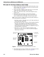
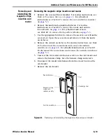
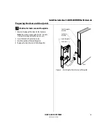
Reinstalling the magnetic stripe insertion card reader
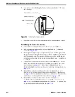
1. Position the card reader in the outside escutcheon and secure it
with the two reader electronics screws. Do not tighten the left
screw.
2. Connect the reader wire harness to the circuit board on the card
reader.
3. Position the harness clamp under the left reader electronics screw.
Tighten the screw.
4. Connect the reader wire harness to the control electronics circuit
board. For mortise instructions, see
. For cylindrical instructions, see
Tighten the RQE rose liner on the door with the through-bolts.
5. Reinstall the outside escutcheon. For mortise instructions, see
Task F. To secure the escutcheons and complete the connections:
. For cylindrical instructions, see
escutcheons and complete the connections:
6. Reinstall the inside lever/knob. For mortise instructions,
see
Task G. To reinstall the inside and outside levers/knobs:
. For cylindrical instructions, see
inside and outside levers/knobs:
7. Reinstall the core and throw member. For mortise instructions, see
Task H. To reinstall the core (EEL and EEU only):
.
For cylindrical instructions, see
Task I. To reinstall the core and
8.
Making sure that the access door does not pinch any wires
, insert
the tabs of the access door into its mating slots and swing the door
closed. Use the appropriate bit driver to secure the access door with
the security screw. Tighten firmly.
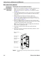
Removing and
reinstalling the
proximity card
reader assembly
Removing the proximity card reader assembly
1. Remove the core and throw member. For mortise instructions, see
. For cylindrical
instructions, see
Task A. To remove the core and throw member:
2. Remove the inside and outside knobs/levers. For mortise
instructions, see
Task B. To remove the inside and outside
. For cylindrical instructions,
see
Task B1. To remove the keyed lever/knob:
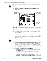
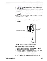
3. Use the appropriate bit driver to remove the security screw from the
access door. Open the access door and remove it from the inside
escutcheon
.
4. Remove the outside escutcheon. For mortise instructions, see
Task D. To disconnect the connections and remove the outside
escutcheon:
. For cylindrical instructions, see
Содержание 34HW
Страница 1: ......
Страница 6: ...Contents vi W Series Service Manual...
Страница 38: ...IDH Max Locks Functions and Parts 2 24 W Series Service Manual...
Страница 54: ...Electrified Locks Functions and Parts 3 16 W Series Service Manual...
Страница 140: ...Service and Maintenance for Cylindrical Locks 5 30 W Series Service Manual...
Страница 158: ...Additional Service and Maintenance for IDH Max Locks 6 18 W Series Service Manual...
Страница 162: ...Glossary A 4 W Series Service Manual...
Страница 164: ...Installation Instructions B 2 W Series Service Manual...