
Installation Instructions for 83KW/93KW–85KW/95KW IDH Max Cylindrical Locks
BEST ACCESS SYSTEMS
Indianapolis, Indiana
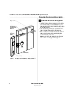
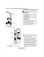
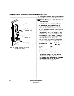
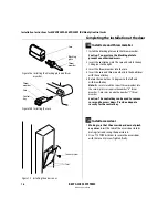
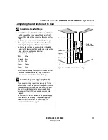
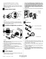
Installing the panel interface module
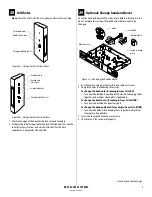
22
25
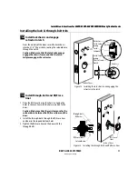
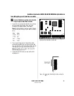
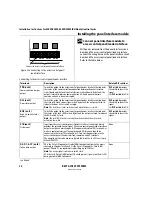
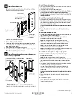
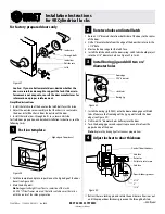
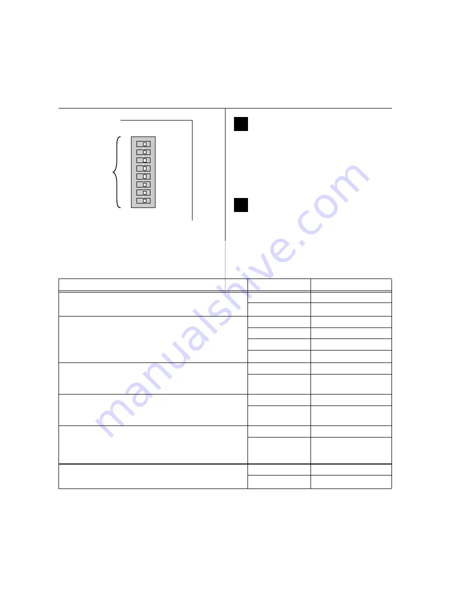
Set panel interface module
DIP switches
Set the DIP switches on the panel interface circuit
board. Refer to the table below. Default settings are
shown in boldface.
Note:
DIP switch 8 is used in IDH Max Mortise
installations. Leave this switch set to ON.
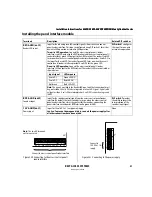
26
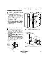
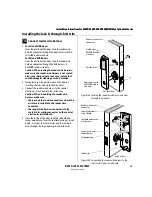
Set and connect power supply
1 Make sure that the output voltage of the power supply
for the panel interface module and lock is set to
15 volts DC or lower.
2 Make the final power supply connections.
3 Adjust the power supply output voltage to
13.8 volts DC.
Feature
Option
DIP Switch Setting
Reader LED input configuration
Provides the ability to select between one-wire and two-wire LED
operation for the reader LED input.
Two-wire operation
Switch 1–ON
One-wire operation
Switch 1–OFF
Baud rate selection
Provides the ability to select the baud rate for communication between the
panel interface circuit board and the lock’s control electronics circuit board.
Note:
To control the baud rate using DIP switches 2 and 3 on the panel
interface circuit board, DIP switches 6 and 7 on the control electronics circuit
board both must be set to ON (automatic baud rate detection).
38400 bps
Switch 2–OFF Switch 3–OFF
19200 bps
Switch 2–ON Switch 3–OFF
9600 bps
Switch 2–OFF Switch 3–ON
2400 bps
Switch 2–ON Switch 3–ON
Request-to-exit (RQE) status output configuration
Provides the ability to invert the request-to-exit (RQE) status signal. If DIP
switch 4 is ON, the contact is closed when the door knob/lever is turned,
activating the RQE switch.
Normally-open (NO)
Switch 4–ON
Normally-closed (NC)
Switch 4–OFF
Door status output configuration
Provides the ability to invert the signal for the door status output. If DIP
switch 5 is ON, the contact is closed when the door is closed (the door
status switch is closed).
Normally-closed (NC)
Switch 5–ON
Normally-open (NO)
Switch 5–OFF
Communication tamper configuration
Provides the ability to invert the signal for the communication tamper
output. If DIP switch 6 is ON, the contact is closed when the
communication connection between the panel interface circuit board and
the lock’s control electronics circuit board is OK.
Normally-closed (NC)
Switch 6–ON
Normally-open (NO)
Switch 6–OFF
Sounder input configuration
Provides the ability to invert the interpretation of the sounder input signal.
The normal input configuration interprets a closed contact as sounder ON.
Normal input
Switch 7–ON
Inverted input
Switch 7–OFF
12
3
4
5
6
7
8
ON
SW1
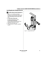
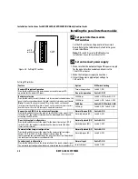
Figure 24 Setting DIP switches
Set DIP
switches.
Setting DIP switches
Содержание 34HW
Страница 1: ......
Страница 6: ...Contents vi W Series Service Manual...
Страница 38: ...IDH Max Locks Functions and Parts 2 24 W Series Service Manual...
Страница 54: ...Electrified Locks Functions and Parts 3 16 W Series Service Manual...
Страница 140: ...Service and Maintenance for Cylindrical Locks 5 30 W Series Service Manual...
Страница 158: ...Additional Service and Maintenance for IDH Max Locks 6 18 W Series Service Manual...
Страница 162: ...Glossary A 4 W Series Service Manual...
Страница 164: ...Installation Instructions B 2 W Series Service Manual...