
Service and Maintenance for Mortise Locks
W Series Service Manual
4–41
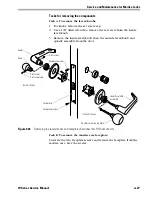
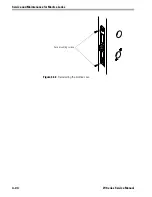
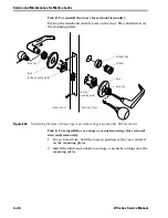
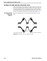
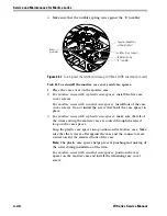
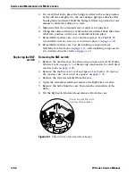
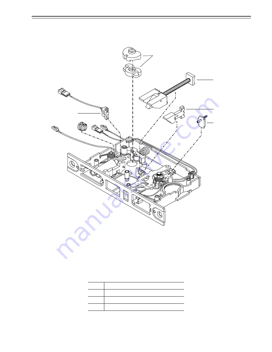
The following diagram and table show which components need to be
turned over when changing the hand and bevel. See the sections that
follow for instructions.
■
B represents the latchbolt and auxiliary bolt.
■
H represents the hubs.
■
C represents the cylinder clamp plate assembly.
■
R represents the request-to-exit switch.
Figure 4.39
Overview of changing the hand and bevel (IDH Max, LHRB orientation shown)
Hubs
Latchbolt
Auxiliary bolt
Cylinder clamp plate
RQE switch
LH
RH
LHRB
RHRB
LH
B/H/C/R B
H/C/R
RH
B/H/C/R
H/C/R
B
LHRB
B
H/C/R
B/H/C/R
RHRB
H/C/R
B
B/H/C/R
Содержание 34HW
Страница 1: ......
Страница 6: ...Contents vi W Series Service Manual...
Страница 38: ...IDH Max Locks Functions and Parts 2 24 W Series Service Manual...
Страница 54: ...Electrified Locks Functions and Parts 3 16 W Series Service Manual...
Страница 140: ...Service and Maintenance for Cylindrical Locks 5 30 W Series Service Manual...
Страница 158: ...Additional Service and Maintenance for IDH Max Locks 6 18 W Series Service Manual...
Страница 162: ...Glossary A 4 W Series Service Manual...
Страница 164: ...Installation Instructions B 2 W Series Service Manual...