BEST ACCESS SYSTEMS 34HW Скачать руководство пользователя страница 111

W Series Service Manual

5–1

S

ERVICE


AND

 M

AINTENANCE


FOR

 C

YLINDRICAL

 L

OCKS

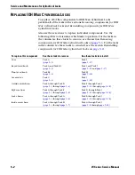
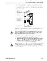
This chapter contains instructions for replacing IDH 
Max and electrified cylindrical components, and 
servicing and maintaining IDH Max and electrified 
cylindrical components.
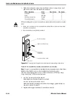
Note:  

When removing and replacing components, 

always test that the lock works properly when 
you’re finished.

Caution

Before you perform any maintenance on your 
lock, make sure that you remove power from the 
lock.

Caution

B

efore you handle the circuit board or any 

component on the circuit board, make sure that 
you are properly grounded using an electrostatic 
discharge (ESD) protection kit. Touching the circuit 
board without proper grounding can damage 
sensitive electronic components—even if you don’t 
notice any static discharge.

If you need to…

See…

Remove components to service the lock

page 5–3

 for IDH Max Locks

page 5–19

 for electrified locks

Replace a component

page 5–2

 for IDH Max Locks

page 5–19

 for electrified locks

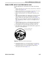
Add the RQE switch to an electrified lock

page 5–25

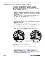
Change the function from electrically-locked to 
electrically-unlocked or from electrically-unlocked to 
electrically-locked

page 5–25

Replace the solenoid

page 5–26

Replace the RQE rose liner

page 5–26

Replace the door status switch and magnet assembly

page 5–28

Change a reader, wire harness, or panel interface module Chapter 6

Содержание 34HW

Страница 1: ......

Страница 2: ...be reproduced or transmitted in any form or by any means electronic or mechanical including photocopying recording or information storage and retrieval systems for any purpose without the express wri...

Страница 3: ...echnical support 1 4 IDH MAX LOCKS FUNCTIONS AND PARTS 2 1 Function descriptions 2 2 IDH Max mortise functions 2 2 IDH Max cylindrical functions 2 4 Trim components 2 5 Proximity card reader and trim...

Страница 4: ...nents diagram 3 15 SERVICE AND MAINTENANCE FOR MORTISE LOCKS 4 1 Replacing components for IDH Max Mortise Locks 4 2 Replacing components for electrified mortise locks 4 25 Removing components for elec...

Страница 5: ...lindrical locks 5 26 Removing and reinstalling the door status switch and magnet assembly for IDH Max Cylindrical Locks 5 28 ADDITIONAL SERVICE AND MAINTENANCE FOR IDH MAX LOCKS 6 1 Replacing wire har...

Страница 6: ...Contents vi W Series Service Manual...

Страница 7: ...on drawings 3 2 Understanding cylindrical function drawings 3 4 Mortise lock components 3 11 Cylindrical lock components 3 14 SERVICE AND MAINTENANCE FOR MORTISE LOCKS Removing the core 4 3 Removing t...

Страница 8: ...lling the mortise case 4 34 Threading the set screw 4 37 Location of the cylinder clamp screw view from the edge of the door 4 38 Explanation of the hand and bevel of the door 4 40 Turning over the hu...

Страница 9: ...r wire harness connector through the wire hole 5 14 Connecting the reader wire harness to the control electronics circuit board 5 15 Securing the through bolt escutcheon and completing connections 5 1...

Страница 10: ...harness cylindrical lock shown 6 2 Removing the harness clamp 6 4 Connecting the wire harnesses to the control electronics circuit board 6 6 Installing the screws for the control electronics circuit b...

Страница 11: ...5KW 95KW DEL DEU function locks CERTIFICATIONS AND STANDARDS IDH Max and electrified locks The 8KW 9KW and 34 37HW locks are UL listed for GYQS electrically controlled single point locks or latches Th...

Страница 12: ...The 36H 37H locks conform to UL437 Standard for Key Locks referencing door locks The 36H 37H high security cylinder complies with ANSI Grade 1 Security and is UL listed UL 437 both in Canada and the U...

Страница 13: ...tallation Instructions for 8K Cylindrical Locks T56066 Wiring Instructions for Cylindrical Locks with Request to Exit T56090 Document Title Doc No W13 Template Installation Specifications for 34HW 35H...

Страница 14: ...es products You may locate the representative nearest you by calling 317 849 2250 Monday through Friday between 7 00 a m and 4 00 p m eastern standard time or visit the web page www BestAccess com H14...

Страница 15: ...The following pages contain function descriptions for all IDH Max Locks This chapter also includes exploded diagrams that show all field serviceable mechanical parts diagrams of trim and other miscell...

Страница 16: ...inside lever knob outside lever knob when electric power is removed from the solenoid outside key Outside lever knob locked by applying 12 VDC to the solenoid remains locked only while power continue...

Страница 17: ...solenoid remains locked only while power continues to be applied Outside lever knob unlocked by removing 12 VDC from the solenoid Inside lever knob is always unlocked Latchbolt operated by inside leve...

Страница 18: ...oved from the solenoid outside key Outside lever knob locked by applying 12 VDC to the solenoid remains locked only while power continues to be applied Outside lever knob unlocked by removing 12 VDC f...

Страница 19: ...Series Service Manual 2 5 TRIM COMPONENTS PROXIMITY CARD READER AND TRIM EXPLODED DIAGRAM Figure 2 3 Proximity card reader and trim exploded diagram 7 9 Outside Inside 3 2 1 1 11 17 12 15 4 6 8 13 14...

Страница 20: ...not shown D62572 1 34HW outside escutcheon for use with non BEST cores or not shown D62567 1 9KW outside escutcheon not shown A60344 1 HID FCC label affixed to the outside escutcheon or not shown A60...

Страница 21: ...2128 1 Access door 25 See page 2 14 1 Access door screw TORX with post head or not shown See page 2 14 1 Access door screw McGard head A61428 a See the H Series Service Manual for other knob styles b...

Страница 22: ...ies Service Manual 2 8 MAGNETIC STRIPE SWIPE CARD READER AND TRIM EXPLODED DIAGRAM Figure 2 4 Magnetic stripe swipe card reader and trim exploded diagram 7 9 Outside Inside 4 2 1 1 6 12 15 23 23 17 3...

Страница 23: ...heon non BEST or not shown D62567 1 9KW outside escutcheon not shown 1773340 1 FCC label affixed to the outside escutcheon 5 A60317 2 Lens cover not shown A60318 2 Lens retaining ring 6 See page 2 13...

Страница 24: ...w TORX with post head or not shown See page 2 14 1 Access door screw McGard head a See the H Series Service Manual for other knob styles b See the H Series Service Manual for other lever styles c See...

Страница 25: ...Parts W Series Service Manual 2 11 MAGNETIC STRIPE INSERTION CARD READER AND TRIM EXPLODED DIAGRAM Figure 2 5 Magnetic stripe insertion card reader and trim exploded diagram 1 1 4 7 9 17 17 11 2 3 6...

Страница 26: ...Bushing 8 B61439 2 Trim hole insert 9 B61326 1 Field wire harness 10 See page 2 13 4 Control electronics mounting screw 11 1805968 1 Cable clamp 12 B61327 1 Sensor and solenoid wire harness 13 B63022...

Страница 27: ...k doors Upper escutcheon screw for 2 thick doors Upper escutcheon screw for 2 1 4 thick doors Upper escutcheon screw for 2 1 2 thick doors Upper escutcheon screw for 2 3 4 thick doors Upper escutcheon...

Страница 28: ...k doors Lower escutcheon screw for 3 thick doors Lower Escutcheon Screw for 1 3 4 Thick Doors Kit 1877702 10 Lower Escutcheon Screw for 2 Thick Doors Kit 1877744 10 Lower Escutcheon Screw for 2 1 4 Th...

Страница 29: ...d 7 are set to ON for automatic baud rate detection This setting lets you determine the baud rate for communication between the lock s control electronics circuit board and the panel interface module...

Страница 30: ...pe card reader see page 6 12 To install the proximity card reader see page 6 15 4 Reinstall the inside and outside escutcheons on the door For mortise lock instructions see page 4 20 For cylindrical l...

Страница 31: ...ions and Parts W Series Service Manual 2 17 MORTISE CASE EXPLODED DIAGRAM Figure 2 7 Mortise case exploded diagram EEU function shown 10 14 17 16 19 26 24 7 9 6 21 22 23 22 25 5 27 29 20 11 4 3 13 8 1...

Страница 32: ...plate 11 A61226 1 Auxiliary bolt spring 12 A18724 2 Case mounting screw 13 A61328 1 Door status switch 14 B34092 1 Auxiliary bolt 15 B61227 1 Latch status switch 16 A61329 1 Latch status switch lever...

Страница 33: ...247 1 Outside mounting plate 4 not shown not shown B61341 B61342 B61343 1 1 1 Concealed cylinder for 1 3 4 2 thick doorsa or Concealed cylinder for 2 1 4 2 1 2 thick doorsa or Concealed cylinder for 2...

Страница 34: ...Functions and Parts 2 20 W Series Service Manual CYLINDRICAL CHASSIS EXPLODED DIAGRAM Figure 2 9 Cylindrical chassis exploded diagram 9K DDEU function shown 6 3 4 5 8 9 10 4 13 12 7 5 14 15 2 11 Insi...

Страница 35: ...or not shown B60420 2 Knob return spring 8KW 5 B55504 2 Thrust plate 6 B60470 1 Wire protector cap 7 B54172 1 Chassis cover not shown A60765 1 ID label affixed to the chassis cover 8 C61034 1 DDEL so...

Страница 36: ...components 8 1 2 3 4 5 10 6 9 7 7 Item Part no Qty Description 1 B34380 1 ANSI plastic strike box 2 B25641 1 ANSI strike plate 3 A18724 2 Screw for ANSI strike 4 not shown C54680 C54684 1 1 Latch for...

Страница 37: ...terface module components parts list Refer to Figure 2 11 and the table below to find the part you need Figure 2 11 Panel interface module components 1 2 Item Part no Qty Description 1 B63023 1 Panel...

Страница 38: ...IDH Max Locks Functions and Parts 2 24 W Series Service Manual...

Страница 39: ...d locks These diagrams show all field serviceable mechanical parts This chapter also includes function descriptions and function conversion information CONVERTING AN EXISTING TRIM STYLE To convert a l...

Страница 40: ...n drawings Outside Inside Outside key Latchbolt Inside key EWEL Electrically Locked Fail Safe EWEU Electrically Unlocked Fail Secure Latchbolt operated by inside lever knob outside lever knob when ele...

Страница 41: ...ide and outside lever knob unlocked by applying 24 VAC VDC to the solenoid remains unlocked only while power continues to be applied YEL Electrically Locked Fail Safe YEU Electrically Unlocked Fail Se...

Страница 42: ...e lever knob outside lever knob when electric power is removed from the solenoid outside key Outside lever knob locked by applying 24 VDC to the solenoid remains locked only while power continues to b...

Страница 43: ...er styles 2 A34131 2 Rose ring for lever trim or not shown B34544 2 Rose ring for knob trim 3 A34129 2 Rosea 4 B35029 1 Mounting plate assembly 5 5 A35455 A35084 1 1 15 outside lever assemblya or 4 ou...

Страница 44: ...Qty Description 1 1 E55169 B54707 1 1 15 plain lever handlea or 4 plain knobb a See the 9K Series Service Manual for other lever styles b See the 8K Series Service Manual for other knob styles 2 B5500...

Страница 45: ...B34543 2 Escutcheon ring for knob trim 3 A35461 1 Inside escutcheon assembly or not shown A35460 1 Inside escutcheon assembly 4 B35029 1 Mounting plate assembly 5 C34413 1 Outside escutcheon 6 6 A3545...

Страница 46: ...r styles 2 A35494 1 Inside escutcheon assembly or not shown A35496 1 Inside escutcheon assembly 3 B35249 1 Mounting plate assembly 4 C34445 1 Outside escutcheon 5 5 A35455 A35084 1 1 15 outside lever...

Страница 47: ...Functions and Parts W Series Service Manual 3 9 MORTISE CASE EXPLODED DIAGRAM Figure 3 7 Mortise case exploded diagram EWEU function shown 7 9 6 20 21 22 21 23 24 5 26 25 27 18 10 4 3 28 11 19 2 1 8...

Страница 48: ...1 Auxiliary bolt spring 11 A18724 2 Case mounting screw 12 B34092 1 Auxiliary bolt 13 A61227 1 Latch status switch 14 A61329 1 Latch status switch lever 15 A61250 2 Latch status switch screw 16 A3423...

Страница 49: ...g plate for A B C D or J trim 4 not shown not shown B61234 B61235 B61236 1 1 1 Concealed cylinder for 1 3 4 2 thick doors a Concealed cylinder for 2 1 4 2 1 2 thick doorsa Concealed cylinder for 2 3 4...

Страница 50: ...cks Functions and Parts 3 12 W Series Service Manual CYLINDRICAL CHASSIS EXPLODED DIAGRAM Figure 3 9 Cylindrical chassis exploded diagram 9K DEU function shown 2 6 3 4 5 7 9 10 11 5 13 12 8 4 14 15 In...

Страница 51: ...shown B60420 1 Knob return spring 8KW 5 B55504 2 Thrust plate 6 B60470 1 Wire protector cap 7 B54172 1 Chassis cover not shown A60227 1 ID label affixed to the chassis cover 8 C60231 1 DEU solenoid o...

Страница 52: ...9 1 2 3 4 5 7 6 10 8 Item Part no Qty Description 1 B34380 1 ANSI plastic strike box 2 B25641 1 ANSI strike plate 3 not shown A18724 A34450 2 2 Screw for ANSI strike Security strike screw 4 B25640 1 S...

Страница 53: ...ow to find the part you need Figure 3 11 8W components diagram 5 7 6 4 3 2 1 Item Nomen clature Description 1 8W599 Transformer 2 8WCON AC to DC converter full wave bridge rectifier 3 8WMOV Metal oxid...

Страница 54: ...Electrified Locks Functions and Parts 3 16 W Series Service Manual...

Страница 55: ...properly grounded using an electrostatic discharge ESD protection kit Touching the circuit board without proper grounding can damage sensitive electronic components even if you don t notice any stati...

Страница 56: ...or IDH Max Mortise Locks which starts on page 4 13 To replace this component See these tasks to remove See these tasks to reinstall Core Task A page 4 3 Task H page 4 23 Inside and outside lever knob...

Страница 57: ...ents for IDH Max Mortise Locks Task A To remove the core Note Only EEL and EEU function locks have a core 1 Insert the control key into the core and rotate the key 15 degrees to the right 2 Remove the...

Страница 58: ...ap and use a 1 8 Allen wrench to remove the set screw from the inside lever knob 2 Remove the inside lever knob then the outside lever knob and spindle assembly from the door Figure 4 2 Removing the k...

Страница 59: ...vice Manual 4 5 Task C To remove the access door 1 Use the appropriate bit driver to remove the security screw from the access door 2 Open the access door and remove it from the escutcheon Figure 4 4...

Страница 60: ...cheon screws from the inside escutcheon Pull the inside escutcheon away from the door enough to expose the control electronics circuit board Note You can let the inside escutcheon dangle from the fiel...

Страница 61: ...and solenoid connection 3 Disconnect the reader wire harness from the control electronics circuit board Figure 4 6 Disconnecting the wire harnesses Reader wire harness connector Sensor wires and sole...

Страница 62: ...emoving the outside escutcheon make sure that the reader wire harness is not rubbed across any sharp edges or over any surface that could damage its sleeving or wire insulation Figure 4 7 Removing the...

Страница 63: ...s Service Manual 4 9 5 Remove the bushings and trim hole inserts from each side of the door Figure 4 8 Removing the trim hole inserts and bushings from the door Outside of door Bushing Trim hole inser...

Страница 64: ...Unscrew the two faceplate screws and remove the faceplate from the mortise case Save the screws 2 Loosen the cylinder clamp screw located inside the mortise case 3 Turn the cylinder counterclockwise...

Страница 65: ...2 Remove the outside and inside mounting plates Task G To remove the mortise case 1 Remove the two case mounting screws 2 Remove the mortise case from the door Figure 4 10 Removing the mounting plate...

Страница 66: ...e 3 Disconnect the leads 4 Remove the inside escutcheon from the door and pull the field wire harness out of the door Caution When removing the inside escutcheon make sure that the field wire harness...

Страница 67: ...through the door to the hinge mortise Note You can let the inside escutcheon dangle from the field wire harness while completing Task A through Task F 3 Trim the four leads of the field wire harness...

Страница 68: ...the mortise cavity while feeding the sensor and solenoid wires into the mortise cavity and out the sensor solenoid wire hole to the inside of the door Note The field wire harness should be routed abo...

Страница 69: ...late opposite the outside mounting plate and screw them securely in place Caution Do not overtighten the mounting plate screws Overtightening may compress the mortise cavity and bind the locking mecha...

Страница 70: ...ore when installed in the cylinder is flush with the outer surface of the escutcheon Caution A malfunction can occur if the cylinder is threaded in too far 2 Secure the cylinder in the mortise case wi...

Страница 71: ...sert the two trim hole inserts into the upper trim hole on each side of the door 2 Insert the two bushings into the field harness reader wire hole on each side of the door Figure 4 18 Reinstalling bus...

Страница 72: ...ask G on page 4 21 6 Connect the reader wire harness to the control electronics circuit board in the inside escutcheon 7 Feed the solenoid and sensor wire harness from the control electronics circuit...

Страница 73: ...reader wire connector the reader wire harness connector is fully seated in its mating connector on the control electronics circuit board Figure 4 20 Connecting the reader wire harness to the control...

Страница 74: ...surface that could damage their sleeving or wire insulation 3 Make the solenoid connection and three sensor connections and place the wires into the inside trim Caution When making the sensor connecti...

Страница 75: ...y For knobs 1 From the outside of the door insert the outside knob and spindle assembly into the lock 2 Slide the inside knob onto the inside spindle and secure it with the set screw 3 Push the set sc...

Страница 76: ...tside lever and spindle assembly into the lock from the outside of the door 2 Slide the inside lever onto the inside spindle and secure it with the set screw 3 Tighten the upper and lower escutcheon s...

Страница 77: ...the cylinder Note If the core does not insert easily into the cylinder loosen the escutcheon screws and reposition the outside escutcheon When the core is inserted fully retighten the escutcheon screw...

Страница 78: ...or 1 Making sure that the access door does not pinch any wires insert the tabs of the access door into its mating slots and swing the door closed 2 Use the appropriate bit driver to secure the access...

Страница 79: ...hrough Task D Task F page 4 27 through page 4 30 Task C Task E through Task H page 4 35 page 4 36 through page 4 39 Escutcheons for M trim Task A through Task C Task F page 4 27 through page 4 28 page...

Страница 80: ...lates page 4 31 7 Perform Task H To remove the mortise case page 4 32 Removing the J trim and mortise case Refer to the trim diagrams on page 3 7 and the detailed instructions for each task listed bel...

Страница 81: ...inside lever knob then the outside lever knob and spindle assembly from the door Task B To remove the mortise case faceplate Unscrew the two faceplate screws and remove the faceplate from the mortise...

Страница 82: ...rotate the key 15 degrees to the right Remove the core 2 Loosen the cylinder clamp screw located inside the mortise case 3 Using a narrow bladed screwdriver insert the blade into the figure 8 opening...

Страница 83: ...ise cylinder wrench into the cylinder and turn it counterclockwise until you can remove the cylinder and cylinder ring 5 If the lock is double keyed repeat step 1 through step 3 on the other side of t...

Страница 84: ...panner wrench into the hole in the inside rose escutcheon ring and rotate counterclockwise until you can remove the inside rose escutcheon ring 2 Repeat step 1 for the outside rose ring Task E To remo...

Страница 85: ...G To remove the mounting plates 1 Remove the two mounting plate screws from the inside of the door Save the screws 2 Remove the outside and inside mounting plates 3 For J trim remove the J alignment p...

Страница 86: ...ons for each task found in Tasks for reinstalling the components Reinstalling the sectional trim and mortise case Refer to the trim diagram on page 3 5 and the detailed instructions for each task list...

Страница 87: ...ll the mortise case faceplate page 4 39 7 Perform Task H To reinstall the levers knobs page 4 39 Reinstalling the M trim and mortise case Refer to the trim diagram on page 3 8 and the detailed instruc...

Страница 88: ...Service and Maintenance for Mortise Locks 4 34 W Series Service Manual Figure 4 32 Reinstalling the mortise case Case mounting screws...

Страница 89: ...stall the escutcheons for J trim and M trim only 1 Position the inside and outside escutcheons on the door 2 Install the upper and lower escutcheon screws from the inside of the door Note The J escutc...

Страница 90: ...tcheon rings for sectional trim and J trim only 1 For sectional trim hold the roses in position so they are centered on the mounting plates 2 Install the inside and outside rose rings or escutcheon ri...

Страница 91: ...t screw into the cylinder until the tip of the set screw is below the threads of the cylinder 2 Make sure that the cylinder ring are positioned on the cylinder 3 With the mortise cylinder wrench inser...

Страница 92: ...se case 6 Insert the control key and core into the cylinder Rotate the control key 15 degrees to the left and then remove the key 7 If the lock is double keyed repeat step 1 through step 4 on the othe...

Страница 93: ...position the lever so that the handle points toward the door hinges 2 Install the inside lever knob onto the inside spindle 3 Use a 1 8 Allen wrench to install the set screw on the inside lever knob 4...

Страница 94: ...the hand and or bevel and detailed instructions for each task Each outline references the detailed instructions for each task found in Tasks for changing the hand and bevel which starts on page 4 43 C...

Страница 95: ...or instructions B represents the latchbolt and auxiliary bolt H represents the hubs C represents the cylinder clamp plate assembly R represents the request to exit switch Figure 4 39 Overview of chang...

Страница 96: ...ge 4 32 Changing the bevel only Refer to the detailed instructions for each task that follows 1 Remove the mortise case See Removing components for IDH Max Mortise Locks on page 4 3 or Removing compon...

Страница 97: ...a flat surface 2 For mortise cases with a plastic case spacer remove the case spacer from the case The plastic case spacer is tension mounted For mortise cases with a metal case spacer remove the case...

Страница 98: ...e case 3 Gently pull the switch bracket feet apart and remove the bracket from the switch 4 Reposition the switch lever For RH RHRB the switch lever pivots at the bottom of the bracket near the feet F...

Страница 99: ...Slide the strain relief into position on the case It should lock into place 7 Tilt the RQE switch forward and slide it into place in the case Task D To reinstall the hubs 1 Push the hub lever toward...

Страница 100: ...e as the mortise cylinder Task F To turn over the auxiliary bolt 1 Remove the auxiliary bolt spring 2 Remove the auxiliary bolt from the case and turn it over 3 Insert the auxiliary bolt into the case...

Страница 101: ...e case 2 Turn over the latchbolt and rotate the anti friction latch lever into position Place the latchbolt in the case 3 Slide the brass grommet on the latchbolt away from the U shaped latchbolt rod...

Страница 102: ...make sure that all of the wires exiting the mortise case are routed through the raised loop on the case spacer Snap the plastic case spacer into position on the mortise case Make sure that the wires...

Страница 103: ...e of the outside hub as shown in Figure 4 48 Note If you need to change the orientation of the RQE switch see step 3 through step 5 Task C To turn over the RQE switch on page 4 44 5 Clamp the RQE swit...

Страница 104: ...the solenoid pin 5 Flip the solenoid and insert the pin of the solenoid plunger into the hole on the locking bar Note For IDH Max Locks the solenoid rests in an opening in the case and is held in plac...

Страница 105: ...in 7 Remove the solenoid from the case Remember the orientation of the solenoid 8 For electrified locks carefully pry the bridge rectifier from the case Remove any adhesive residue from the case Reins...

Страница 106: ...48 8 Reinstall the mortise case See Reinstalling components for IDH Max Mortise Locks on page 4 13 or Reinstalling components for electrified mortise locks on page 4 32 Replacing the RQE switch Remov...

Страница 107: ...the hubs The flat side of the outside hub should be opposite the pivot point on the RQE switch 5 Reinstall the mortise case cover and case spacer See Task H To reinstall the mortise case cover and cas...

Страница 108: ...r cable in the strain relief Slide the strain relief into position on the case It should lock into place 4 Reinstall the mortise case cover and case spacer See Task H To reinstall the mortise case cov...

Страница 109: ...ire or cable 5 Slide the brass grommet on the latchbolt away from the U shaped latchbolt rod support Grasp the latchbolt by the square shaped tail and pull the latchbolt up and out of the case Maintai...

Страница 110: ...pport Rest the latchbolt rod into the U shaped support Release the grommet It should snap into place Note If you can pull the square shaped tail out of the rod support the latchbolt is not placed prop...

Страница 111: ...ounded using an electrostatic discharge ESD protection kit Touching the circuit board without proper grounding can damage sensitive electronic components even if you don t notice any static discharge...

Страница 112: ...e section Reinstalling components for IDH Max Cylindrical Locks on page 5 8 To replace this component See these tasks to remove See these tasks to reinstall Core Task A page 5 3 Task I page 5 17 Keyed...

Страница 113: ...yed lever knob 1 Insert a flat blade screwdriver into the figure 8 core hole and into the lever knob keeper 2 Press the screwdriver blade in the direction of the arrow shown in Figure 5 2 Note You wil...

Страница 114: ...t from the inside escutcheon Task D To disconnect the connections and remove the outside escutcheon 1 Remove the upper escutcheon and lower escutcheon screws from the inside escutcheon Pull the inside...

Страница 115: ...ness is not rubbed across any sharp edges or over any surface that could damage its sleeving or wire insulation Figure 5 5 Loosening the escutcheon and disconnecting the connections Inside of door Rea...

Страница 116: ...the door Task F To remove the RQE rose liner 1 Remove the through bolts from the top and bottom holes in the RQE rose liner 2 Slide the rose liner off the door Task G To remove the lock chassis Slide...

Страница 117: ...nect the leads 4 Remove the inside escutcheon from the door and pull the field wire harness out of the door Caution When removing the inside escutcheon make sure that the field wire harness is not rub...

Страница 118: ...there are 3 to 4 of slack in the field wire harness to allow access to the control electronics circuit board in the inside escutcheon Note You can let the inside escutcheon dangle from the field wire...

Страница 119: ...h pair of leads to its corresponding field wire 7 Insert the wires and splice connectors into the holes or pockets in the door and frame being careful not to pinch the wires Install the wire transfer...

Страница 120: ...tside rose liner until the proper groove on the through bolt stud lines up with the hub face Note 1 Make sure that the locking pin fully locks into the rose liner Note 2 The lock fits doors 1 3 4 to 2...

Страница 121: ...tailpiece engages the retractor Task D To reinstall the RQE rose liner 1 Place the RQE rose liner on the chassis aligning the holes in the rose liner with the holes prepared in the door Caution Make s...

Страница 122: ...oor 2 For LH and LHRB doors Insert two bushings into the door status switch LH LHRB reader wire hole on each side of the door For RH and RHRB doors Insert two bushings into the field harness RH RHRB r...

Страница 123: ...3 4 On each side of the door slide a hub washer over the chassis sleeve so it rests on the hub Figure 5 14 Reinstalling trim hole inserts bushings and hub washers Bushing Trim hole insert Outside of d...

Страница 124: ...Temporarily rest the outside escutcheon on the door by inserting the escutcheon studs into the trim holes 3 Connect the reader wire harness to the control electronics circuit board in the inside escut...

Страница 125: ...outside escutcheons onto the door 2 Making sure that the escutcheon does not pinch the wires secure the escutcheons to the door but do not tighten Use the upper escutcheon screw at the top escutcheon...

Страница 126: ...KW Lock see the Installation Instructions for 9K Non interchangeable Cores Throw Members T56093 Skip Step 4 and Step 5 of those instructions 1 For the inside and outside knobs Push firmly on the knob...

Страница 127: ...ll the blocking plate onto the throw member Caution You must use the blocking plate to prevent unauthorized access 2 Insert the control key into the core and rotate the key 15 degrees to the right 3 I...

Страница 128: ...ember Caution The control key can be used to remove cores and to access doors Provide adequate security for the control key Task J To reinstall the access door 1 Making sure that the access door does...

Страница 129: ...or electrified cylindrical locks Task A To remove the core 1 Insert the control key into the core and rotate the key 15 degrees to the right 2 Remove the core and throw member from the lever knob To r...

Страница 130: ...move the lever knob if the screwdriver blade is inserted too far past the keeper 3 Slide the lever knob off the sleeve Task B2 To remove the plain lever knob Insert the protrusion on the spanner wrenc...

Страница 131: ...wn in Figure 5 25 Pry the rose until it pops off the liner 2 Unscrew the two through bolts as shown in Figure 5 26 Save the through bolts 3 If there is an RQE rose liner disconnect it 4 Slide the line...

Страница 132: ...bly 1 Retract the rose locking pin and rotate the rose and liner assembly clockwise until the proper door thickness groove on the through bolt stud lines up with the hub face 2 Release the rose lockin...

Страница 133: ...Task B To reinstall the inside rose and rose liner 1 Align the holes in the liner with the holes prepared in the door 2 Install the two through bolts through the liner and door in the top and bottom h...

Страница 134: ...Turn the levers knobs to check that they operate smoothly Task D To reinstall the core 1 Insert the control key into the core and rotate the key 15 degrees to the right 2 Using the control key insert...

Страница 135: ...indrical chassis Contact your BEST representative Use the following part numbers when ordering a new cylindrical chassis Chassis type Part number 8KW DEL C60247 8KW DEU C60243 9KW DEL C60245 9KW DEL n...

Страница 136: ...the RQE rose liner 1 For IDH Max Locks Remove the access door See Task C To remove the access door on page 5 4 Remove the inside lever knob See Task B1 To remove the keyed lever knob on page 5 3 Remov...

Страница 137: ...RQE rose liner and door in the top and bottom holes 3 Tighten the RQE rose liner on the door with the through bolts 4 Connect the RQE connector 5 For IDH Max Locks Reinstall the inside hub washer Rein...

Страница 138: ...e upper and lower escutcheon screws from the inside escutcheon Note You can let the inside escutcheon dangle from the field wire harness while completing this task 4 Disconnect the door status switch...

Страница 139: ...arness 4 Reinstall the upper and lower escutcheon screws on the inside escutcheon 5 Reinstall the inside lever knob See Task H To reinstall the inside and outside levers knobs on page 5 16 6 Reinstall...

Страница 140: ...Service and Maintenance for Cylindrical Locks 5 30 W Series Service Manual...

Страница 141: ...e the circuit board or any component on the circuit board make sure that you are properly grounded using an electrostatic discharge ESD protection kit Touching the circuit board without proper groundi...

Страница 142: ...inside and outside levers knobs on page 4 4 For cylindrical instructions see Task B2 To remove the plain lever knob on page 5 4 4 Remove the upper and lower escutcheon screws from the inside escutche...

Страница 143: ...r closed Use the appropriate bit driver to secure the access door with the security screw Tighten firmly Removing and reinstalling the reader wire harness Removing the reader wire harness To replace a...

Страница 144: ...ed 4 Connect the reader wire harness to the control electronics circuit board For mortise instructions see Task E To connect the reader wire harness on page 4 17 For cylindrical instructions see Tight...

Страница 145: ...se the appropriate bit driver to remove the security screw from the access door Open the access door and remove it from the inside escutcheon 4 Loosen the inside escutcheon and disconnect the connecti...

Страница 146: ...e damaged or not operate properly without the strain relief 3 Pull the field wire harness through the door and connect the field wire harness to the wire transfer hinge For mortise instructions see Ta...

Страница 147: ...ecure the escutcheons and complete the connections on page 5 15 7 Reinstall the inside lever knob For mortise instructions see Task G To reinstall the inside and outside levers knobs on page 4 21 For...

Страница 148: ...on the control electronics circuit board By default switches 1 through 5 are set to ON These switches are for possible future applications By default switches 6 and 7 are set to ON for automatic baud...

Страница 149: ...rs knobs on page 4 4 For cylindrical instructions see Task B1 To remove the keyed lever knob on page 5 3 3 Use the appropriate bit driver to remove the security screw from the access door Open the acc...

Страница 150: ...ircuit board is covered 7 Connect the reader wire harness to the control electronics circuit board For mortise instructions see Task E To connect the reader wire harness on page 4 17 For cylindrical i...

Страница 151: ...n page 5 3 2 Remove the inside and outside knobs levers For mortise instructions see Task B To remove the inside and outside levers knobs on page 4 4 For cylindrical instructions see Task B1 To remove...

Страница 152: ...from the edge of the escutcheon gasket and slide the gasket onto the upper escutcheon post Press the gasket into place on the edge of the escutcheon so the reader circuit board is covered 7 Connect th...

Страница 153: ...5 3 3 Use the appropriate bit driver to remove the security screw from the access door Open the access door and remove it from the inside escutcheon 4 Remove the outside escutcheon For mortise instruc...

Страница 154: ...and outside levers knobs on page 5 16 7 Reinstall the core and throw member For mortise instructions see Task H To reinstall the core EEL and EEU only on page 4 23 For cylindrical instructions see Ta...

Страница 155: ...outside escutcheon 8 Unscrew the four bezel mounting screws Save the screws 9 Remove the proximity card reader assembly from the outside escutcheon Reinstalling the proximity card reader assembly 1 Or...

Страница 156: ...te the connections on page 4 20 For cylindrical instructions see Task G To secure the escutcheons and complete the connections on page 5 15 9 Reinstall the outside escutcheon For mortise instructions...

Страница 157: ...s control panel reader interface 2 Slide the panel interface circuit board out of the panel rail 3 Slide the new panel interface circuit board into the panel rail 4 Reconnect the connections running t...

Страница 158: ...Additional Service and Maintenance for IDH Max Locks 6 18 W Series Service Manual...

Страница 159: ...aceplate to the center of the cylinder or lever knob Cam See Cylinder cam Card reader A device that reads the information encoded on magnetic stripe cards or proximity cards Core See Interchangeable c...

Страница 160: ...ce that contains all mechanical parts for a masterkeyed system The interchangeable core can be removed by a special control key and can be recombinated without disassembling the lock See also Figure 8...

Страница 161: ...le or sound an alarm start a timer etc Reverse bevel See Hand of door Solenoid A component that operates the locking mechanism of the lock Sounder The device in the lock that produces sound The sounde...

Страница 162: ...Glossary A 4 W Series Service Manual...

Страница 163: ...nstallation Instructions for 83KW 93KW 85KW 95KW IDH Max Cylindrical Locks Installation Instructions for 34H 37H Mortise Locks Wiring Instructions for 34HW 37HW Series Electrically operated Mortise Lo...

Страница 164: ...Installation Instructions B 2 W Series Service Manual...

Страница 165: ...erfaces contact your local BEST representative A panel interface module is provided with the lock The panel interface module receives token data and lock sensor data from the lock through an RS 485 co...

Страница 166: ...or test requirements for ANSI BHMA 156 25 Side of door Range Inside 66 F to 74 F 19 C to 23 C Outside 31 F to 151 F 35 C to 66 C Side of door Range Inside and outside 32 F to 120 F 0 C to 49 C Use the...

Страница 167: ...ng The distance from the power supply to the first door If powering more than one door daisy chained to the same power supply add the total distance of the power runs between the doors Refer to the ta...

Страница 168: ...he door 2 On the door s edge and door jamb mark the vertical centerline of the lock 3 Measure and mark the backset 2 3 4 standard from the vertical centerline on the door s edge On both sides of the d...

Страница 169: ...lock case and faceplate 1 Mortise the edge of the door for the lock case Note The mortise cavity depth of 4 5 8 includes clearance for wiring behind the mortise case 2 Insert the lock in the mortise c...

Страница 170: ...oor sensor solenoid wire hole 7 8 diameter from inside into mortise cavity approximately 1 deep Note 1 To locate the center of a hole on the opposite side of the door drill a pilot hole completely thr...

Страница 171: ...iring 1 Drill a wire access hole through the frame side of the hinge mortise 2 Drill holes or pockets for splice connectors in the frame and door Refer to the hinge manufacturer s specifications for t...

Страница 172: ...ld wire harness through door 1 Feed the field wire harness connected to the inside trim into the field harness reader wire hole and down into the mortise cavity 2 From the hinge edge of the door fish...

Страница 173: ...y 3 Make sure there are 3 to 4 of slack in the field wire harness to allow access to the control electronics circuit board in the inside trim 4 Secure the mortise case with the case mounting screws 10...

Страница 174: ...the cylinder depth plus or minus one 1 turn so that the core when installed in the cylinder is flush with the outer surface of the trim Caution A malfunction can occur if the cylinder is threaded in...

Страница 175: ...switches on the control electronics circuit board located in the inside escutcheon By default switches 1 through 5 are set to ON These switches are for possible future applications By default switche...

Страница 176: ...ge opening in the inside trim Figure 13a Feeding the reader wire harness connector from the outside trim through the door Reader wire harness connector Field harness reader wire hole Outside trim Outs...

Страница 177: ...ss the sensor wires and the solenoid wires make sure the wires are not routed across any sharp edges or over any surface that could damage their sleeving or wire insulation 3 Make the solenoid connect...

Страница 178: ...t with the set screw 3 Push the set screw cap into the set screw hole 4 Tighten the trim mounting screws 5 Turn the knobs to check that they operate smoothly For levers 1 With the handle pointing towa...

Страница 179: ...the cylinder 3 Rotate the control key 15 degrees to the left and withdraw the key Caution The control key can be used to remove cores and to access doors Provide adequate security for the control key...

Страница 180: ...n the frame side of the hinge following the hinge manufacturer s instructions 3 Splice the four field wire harness wires listed in the table below to the four pairs of leads on the door side of the hi...

Страница 181: ...g the latch open when the door is closed If the incorrect strike is installed a lock in can occur Note The recommended gap between the door and jamb is 1 8 20 Install lock power supply optional If you...

Страница 182: ...edtothedoor side of the wire transfer hinge are described in the table below 2 If you are providing power to the lock through the panel interface module connect the two power field wires run from the...

Страница 183: ...IP switch 8 to serve one of two possible functions Option 1 Door status latchbolt status output Indicates whether the dooris secure both the door status and latchbolt status switchesare closed or unse...

Страница 184: ...access control panel s reader interface s LED output to the RED terminal The reader s LEDs are controlled as shown below Note The signals provided to the Reader LED input and the Sounder input must be...

Страница 185: ...tch 3 OFF 19200 bps Switch 2 ON Switch 3 OFF 9600 bps Switch 2 OFF Switch 3 ON 2400 bps Switch 2 ON Switch 3 ON Request to exit RQE status output configuration Provides the ability to invert the reque...

Страница 186: ...closed contact as sounder ON Normal input Switch 7 ON Inverted input Switch 7 OFF Function of TPR terminals and DLS terminals Provides the ability to determine the function of the TPR terminals and D...

Страница 187: ...and verify that the information recorded for the token is correct 3 Use an invalid token to attempt to access the lock Confirmthatthe red reader LED green readerLED and sounder respond as expected Th...

Страница 188: ...s DIP switches 2 and 3 on the panel interface circuit board Check the connections for all communication field wiring Check the communication connections between the field wire harness and the wire tra...

Страница 189: ...interface module is provided with the lock The panel interface module receives token data and lock sensor data from the lock through an RS 485 connection It translates this data into parallel signals...

Страница 190: ...t requirements for ANSI BHMA 156 25 Side of door Range Inside 66 F to 74 F 19 C to 23 C Outside 31 F to 151 F 35 C to 66 C Side of door Range Inside and outside 32 F to 120 F 0 C to 49 C Use the follo...

Страница 191: ...g The distance from the power supply to the first door If powering more than one door daisy chained to the same power supply add the total distance of the power runs between the doors Refer to the tab...

Страница 192: ...l centerline of the door edge Note The recommended height from the floor to the centerline of the lock is 38 2 Fold the W16 Template Installation Template for 83KW 93KW IDH Max Cylindrical Locks on th...

Страница 193: ...hole solenoid wire hole 3 8 diameter through door before drilling chassis hole chassis hole 2 1 8 diameter through door after drilling solenoid wire hole latch hole 1 diameter meets chassis hole Note...

Страница 194: ...e access hole through the frame side of the hinge mortise 2 Drill holes or pockets for the splice connectors in the frame and door Refer to the hinge manufacturer s specifications for the hole locatio...

Страница 195: ...h bolt holes 9KW only 1 Press the drill jig KD303 onto the door engaging it with the latch tube prongs Make sure the front edge of the jig is parallel with the door edge 2 Drill the through bolt holes...

Страница 196: ...hrough the door to the hinge mortise 2 From the latch edge of the door fish the field wire harness through the door to the hinge mortise 3 Make sure there are 3 to 4 of slack in the field wire harness...

Страница 197: ...ire hole to the inside of the door as shown in Figure 8 9 Install strike box and strike plate 1 In alignment with the center of the latchbolt mortise the door jamb to fit the strike box and strike pla...

Страница 198: ...e is inserted too far past the keeper 4 Slide the knob lever off of the sleeve 11 Adjust for door thickness 1 Determine the door s thickness 2 Pull the rose locking pin and rotate the outside rose lin...

Страница 199: ...Install through bolts and RQE rose liner 1 Place the RQE rose liner on the chassis aligning the holes in the rose liner with the holes prepared in the door Caution Make sure that there is clearance f...

Страница 200: ...is sleeve so it rests on the hub Note You do not need to change the positions of the DIP switches on the control electronics circuit board located in the inside escutcheon By default switches 1 throug...

Страница 201: ...nect the reader wire harness to the control electronics circuit board in the inside trim Caution When connecting the reader wire harness make sure there are no loose wire connections where the wires a...

Страница 202: ...e solenoid wires make sure the wires are not routed across any sharp edges or over any surface that could damage their sleeving or wire insulation 3 Make the three 3 sensor connections and solenoid co...

Страница 203: ...om a manufacturer other than BEST with a 9KW Lock see the Installation Instructions for 9K Non interchangeable Cores Throw Members T56093 Skip task 17 and task 18 1 For the inside and outside knobs Pu...

Страница 204: ...and withdraw the key Note Be sure to insert the correct throw member into the core 6 pin cores require the number 6 throw member 7 pin cores require the number 7 throw member Caution The control key c...

Страница 205: ...nge matching each pair of leads to its corresponding field wire 4 Insert the wires and splice connectors into the holes or pockets in the door and frame being careful not to pinch the wires Install th...

Страница 206: ...nterface module 18 22 Mount panel interface module Peel the paper off the adhesive tape affixed to the back of the panel rail and press the panel rail into position Note Mount the panel interface modu...

Страница 207: ...ribed in the table below 2 If you are providing power to the lock through the panel interface module connect the two power field wires run from the wire transfer hinge to the 12V and GND terminals on...

Страница 208: ...tch 8 to ON RQE on J3 Request to exit status output Switch like output to the access control panel reader interface that indicates the status of the lock s RQE switch By default the output is closed t...

Страница 209: ...Reader LED input and the Sounder input must be greater than 3 5 volts DC to be interpreted as a 5 volts DC signal Signals with voltage less than 8 volts DC are interpreted as 0 volts DC connection to...

Страница 210: ...t board both must be set to ON automatic baud rate detection 38400 bps Switch 2 OFF Switch 3 OFF 19200 bps Switch 2 ON Switch 3 OFF 9600 bps Switch 2 OFF Switch 3 ON 2400 bps Switch 2 ON Switch 3 ON R...

Страница 211: ...eader LED green readerLED and sounder respond as expected The lock should allow access verifying that the solenoid is working To check that the reader is working view the lock s event history and veri...

Страница 212: ...he same positions as DIP switches 2 and 3 on the panel interface circuit board Check the connections for all communication field wiring Check the communication connections between the field wire harne...

Страница 213: ...he appropriate drill points 27 Install strike plate 1 Mortise the door jamb for the strike box and strike plate When the strike box is not used mortise the jamb deep enough to allow the latchbolt and...

Страница 214: ...hree steps To change the hand only for example from LH to RH Turn over the latchbolt auxiliary bolt hubs while keeping them together and cylinder clamp plate if applicable To change the bevel only for...

Страница 215: ...the upper and lower escutcheon screws from the inside of the door Note The J escutcheon only has an upper escutcheon screw 3 If there are escutcheon or rose rings use the spanner wrench to install the...

Страница 216: ...nto the tapered inside spindle 3 Turn the set screw until it makes contact with the spindle Then tighten the set screw approximately 3 4 of a turn 4 Push the set screw cap into the set screw hole 5 Tu...

Страница 217: ...Dashed wire lines represent components that MAY OR MAY NOT be required Figure 37 Wiring diagram for the 34 37H electrically operated lock 8WTCM Supplied with electri cally locked EL func tions optiona...

Страница 218: ...he intersection of current and footage The line above or to the right of the intersection shows what minimum gauge wire you need Example Lock current 0 750 amp maximum Total wire run 500 feet Wire gau...

Страница 219: ...the door to the center of the door 2 Drill a 1 diameter hole from the edge of the door that intersects the 2 1 8 hole 3 Mortise the door edge for the latch face 4 Install the latch and check the door...

Страница 220: ...plate 1 In alignment with the center of the latch bolt mortise the door jamb to fit the strike box and strike plate Caution The deadlocking plunger of the latch bolt must not enter thestrike plate The...

Страница 221: ...hinge 8WMOV Metal oxide varistor 8WCON AC to DC converter full wave bridge rectifier Wiring diagram The diagram below shows how to wire 8K and 9K electrified locks Figure 45 Wiring diagram for 8K and...

Страница 222: ...tion of current and footage The line above or to the right of the intersection shows what minimum gauge wire you need Example Lock current 0 169 amp maximum Total wire run 1000 feet Wire gauge needed...

Страница 223: ...42 changing hand and bevel with RQE switch 4 42 bushing part drawings for 2 5 2 8 2 11 part numbers for 2 6 2 9 2 12 reinstalling 4 17 5 12 removing 4 9 5 6 C cable clamp part drawings for 2 5 2 8 2...

Страница 224: ...EU chassis function conversion for 3 13 function description for 3 4 trim conversion for 3 6 disconnecting reader wire harness 4 6 5 4 sensor and solenoid wire harness 4 6 5 4 documentation package 1...

Страница 225: ...part numbers and drawings for 3 7 reinstalling 4 33 removing 4 26 K key release cam assembly part drawings for 2 20 3 12 part numbers for 2 21 3 13 keyed knob see knob keyed lever see lever keyed slee...

Страница 226: ...2 23 part numbers and drawings for 8W components 3 15 for other cylindrical lock components 2 22 3 14 for other mortise lock components 2 19 3 11 for panel interface module 2 23 part numbers and drawi...

Страница 227: ...face circuit board 6 17 proximity card reader 6 14 reader circuit board assembly 6 9 reader wire harness 6 3 rose 4 30 5 21 rose liner 5 21 rose ring 4 30 RQE rose liner 5 6 5 26 RQE switch 4 52 secti...

Страница 228: ...transformer 3 15 trim conversion for DDEL chassis 2 6 2 9 2 12 for DDEU chassis 2 6 2 9 2 12 for DEL chassis 3 6 for DEU chassis 3 6 for EEL case 2 6 2 9 2 12 for EEU case 2 6 2 9 2 12 for EWEL case 3...

Отзывы: