Installation Instructions for 34HW–35HW IDH Max Mortise Locks
BEST ACCESS SYSTEMS
Indianapolis, Indiana
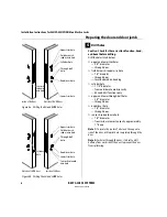
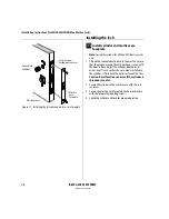
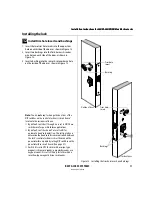
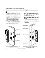
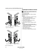
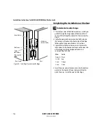
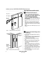
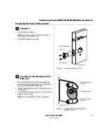
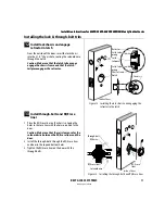
Installing the panel interface module
20
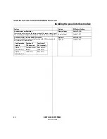
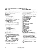
D0, D1, & CP (on J2)
Token data output
D0 is the Data 0 (Wiegand) or Strobe (ABA) token data output to the access
control panel/reader interface. D1 is the Data 1 (Wiegand) or Data (ABA)
output. D0 and D1 are capable of transmitting up to 250 feet.
Note:
The strobe signal is sometimes called ‘clock’.
CP is the Card Present (ABA) output. The card present signal is low (0 volts DC)
during output of ABA token data.
None
RED & GRN (on J2)
Reader LED input
Input for the red and green LED control signal(s) from the access control panel/
reader interface. This input is configured using DIP switch 1 for either one-wire
LED operation or two-wire LED operation.
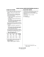
Two-wire LED operation:
Connect the access control panel’s/reader
interface’s red LED output to the RED terminal and the access control panel’s/
reader interface’s green LED output to the GRN terminal. The reader’s red LED
turns on when the access control panel/reader interface provides 0 volts DC to
the input for the red LED. The reader’s green LED turns on when the access
control panel/reader interface provides 0 volts DC for the green LED.
One-wire LED operation:
Connect the access control panel’s/reader
interface’s LED output to the RED terminal. The reader’s LEDs are controlled as
shown below.
Note:
The signals provided to the Reader LED input and the Sounder input must
be greater than 3.5 volts DC to be interpreted as a 5 volts DC signal. Signals with
voltage less than .8 volts DC are interpreted as 0 volts DC (connection to ground
(GND).
DIP switch 1
configures this input
for one-wire or two-
wire operation.
BPR & GND (on J2)
Sounder input
Input for the sounder control signal from the access control panel/reader
interface. By default, the lock’s sounder turns on when the access control
panel/reader interface closes the contact for the sounder, connecting the
panel interface circuit board’s BPR terminal to ground (GND).
DIP switch 7
provides
the ability to invert the
interpretation of the
sounder input signal.
12V & GND (on J1)
Power input
Input for 12 volts DC at .1 amp power supply.
Caution:
To prevent damage and injury, connect the power supply after
all other connections have been made.
None
Terminals
Description
Related DIP switches
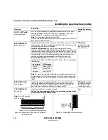
Input signal
LED response
0 volts DC
Green LED ON
5 volts DC
Red LED ON
Not driven
Both LEDs OFF
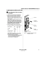
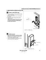
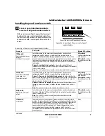
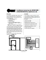
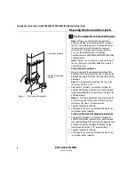
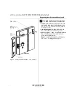
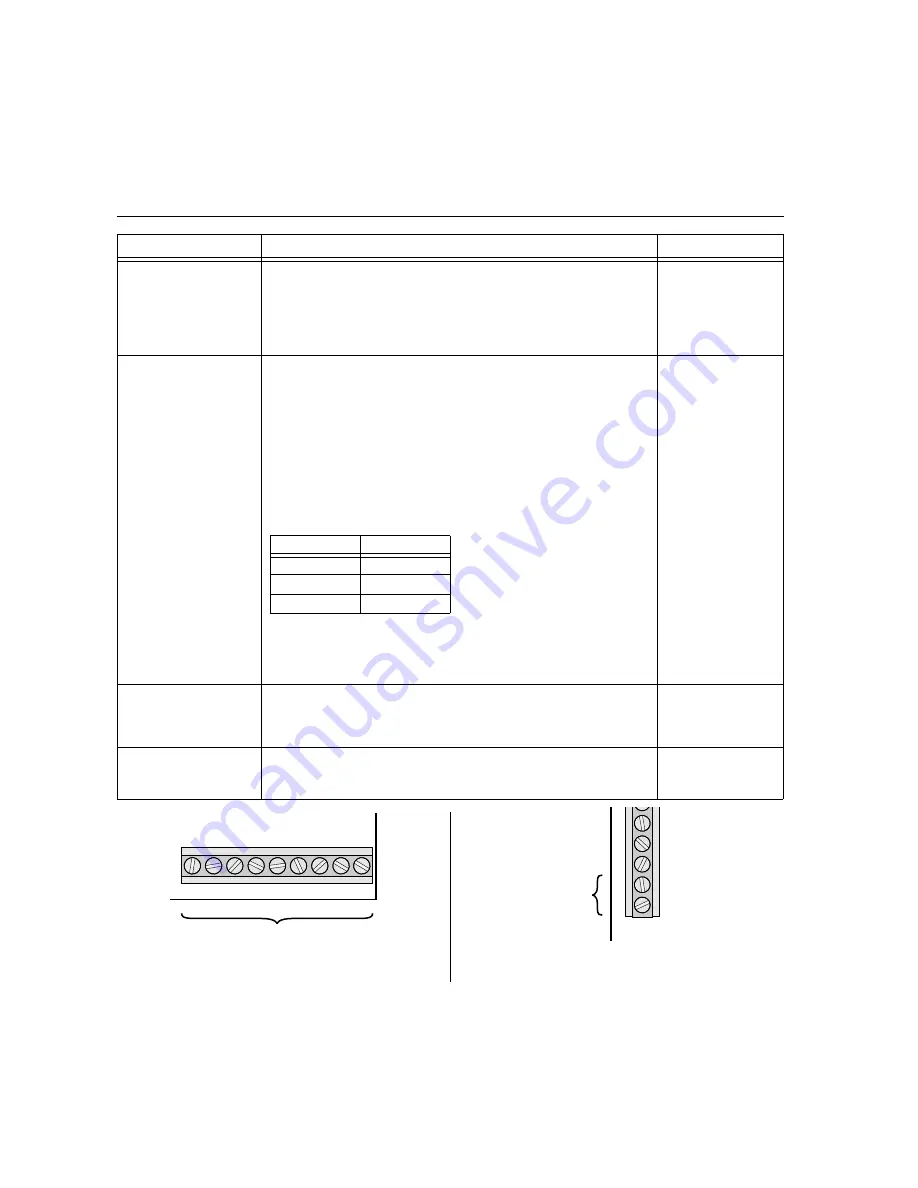
Figure 22b Connecting to the access control panel/
reader interface
J2
D0 D1 RED GRN BPR GND
NC CP
NC
Connect to access control panel/reader interface.
Note:
The two NC terminals
on J2 are not used.
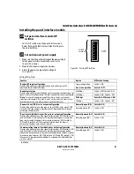
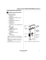
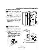
GND
J1
V
COM+
COM-
GND
12V
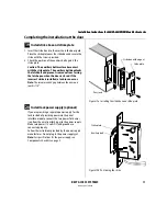
Figure 22c Connecting to the power supply
Connect to
12 VDC at .1 A
supply.
Содержание 34HW
Страница 1: ......
Страница 6: ...Contents vi W Series Service Manual...
Страница 38: ...IDH Max Locks Functions and Parts 2 24 W Series Service Manual...
Страница 54: ...Electrified Locks Functions and Parts 3 16 W Series Service Manual...
Страница 140: ...Service and Maintenance for Cylindrical Locks 5 30 W Series Service Manual...
Страница 158: ...Additional Service and Maintenance for IDH Max Locks 6 18 W Series Service Manual...
Страница 162: ...Glossary A 4 W Series Service Manual...
Страница 164: ...Installation Instructions B 2 W Series Service Manual...