page 80
page 80
page 80
page 80
page 80
160B&C TM
800-00140
E. LUBRICATION
E. LUBRICATION
E. LUBRICATION
E. LUBRICATION
E. LUBRICATION
Internal lubrication is provided by the fluid in the system. Lubrication of the shaft couplings should be as
specified by their manufacturers.
F. REPLACEMENT PARTS
F. REPLACEMENT PARTS
F. REPLACEMENT PARTS
F. REPLACEMENT PARTS
F. REPLACEMENT PARTS
Reliable operation throughout the specified operating range is assured only if genuine parts are used. Sophisticated
design processes and material are used in the manufacture of our parts. Substitutions may result in early failure.
Part numbers are shown in the parts catalogs.
G. TROUBLE SHOOTING
G. TROUBLE SHOOTING
G. TROUBLE SHOOTING
G. TROUBLE SHOOTING
G. TROUBLE SHOOTING
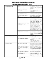
Table 1 lists the common difficulties experienced with vane pumps and hydraulic systems. It also indicates the
probable causes and remedies for each of the troubles listed. It should always be remembered that many apparent
pump failures are actually the failures of other parts of the system. The cause of improper operation is best diagnosed
with adequate testing equipment and a thorough understanding of the complete hydraulic system.
SECTION VI - OVERHAUL
SECTION VI - OVERHAUL
SECTION VI - OVERHAUL
SECTION VI - OVERHAUL
SECTION VI - OVERHAUL
WARNING
WARNING
WARNING
WARNING
WARNING
Before breaking a circuit connection, make certain
Before breaking a circuit connection, make certain
Before breaking a circuit connection, make certain
Before breaking a circuit connection, make certain
Before breaking a circuit connection, make certain
that power is off and system pressure has been
that power is off and system pressure has been
that power is off and system pressure has been
that power is off and system pressure has been
that power is off and system pressure has been
released. Lower all vertical cylinders, discharge
released. Lower all vertical cylinders, discharge
released. Lower all vertical cylinders, discharge
released. Lower all vertical cylinders, discharge
released. Lower all vertical cylinders, discharge
accumulators and block any load whose movement
accumulators and block any load whose movement
accumulators and block any load whose movement
accumulators and block any load whose movement
accumulators and block any load whose movement
could generate pressure.
could generate pressure.
could generate pressure.
could generate pressure.
could generate pressure.
A. GENERAL
A. GENERAL
A. GENERAL
A. GENERAL
A. GENERAL
Plug all removed units and cap all lines to prevent the entry of dirt into the system. During disassembly, pay particular
attention to identification of the parts, especially the cartridges, for correct assembly.
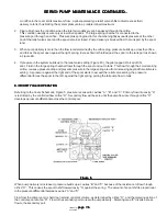
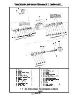
Pump bearings are pressed in the bodies or on the shafts and should not be removed unless defective. Figure 8 is
an exploded view which shows the proper relationship of the parts for disassembly and assembly. Refer to Figure
1 and Figure 8 for the correct assembled relationship of the parts.
B. DISASSEMBLY
B. DISASSEMBLY
B. DISASSEMBLY
B. DISASSEMBLY
B. DISASSEMBLY
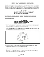
1. Disassembly of Basic Pump-See Figure 8. If a foot bracket is used, remove before dismantling the
pump. Clamp the pump body in a vise (not too tightly), cover end up, and remove the four cover screws.
Note the position of the cover port with respect to the body port before lifting off the cover and o-ring.
(See paragraph 2 for disassembly of flow control covers and paragraph 3 for disassembly of the priority
valve covers).
Remove the pressure plate and spring. Note the position of the ring for correct reassembly. Lift off the
ring and remove the locating pins. Separate the vanes from the rotor and remove the rotor from the
shaft.
SERVO PUMP MAINTENANCE CONTINUED...
SERVO PUMP MAINTENANCE CONTINUED...
SERVO PUMP MAINTENANCE CONTINUED...
SERVO PUMP MAINTENANCE CONTINUED...
SERVO PUMP MAINTENANCE CONTINUED...

