page 75
page 75
page 75
page 75
page 75
160B&C TM
800-00140
B. HYDRAULIC BALANCE
B. HYDRAULIC BALANCE
B. HYDRAULIC BALANCE
B. HYDRAULIC BALANCE
B. HYDRAULIC BALANCE
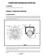
The pump cam ring is shaped so that the two pumping chambers are formed diametrically opposed. Thus, hydraulic forces
which would impose side loads on the shaft are cancelled.
C. PRESSURE PLATE
C. PRESSURE PLATE
C. PRESSURE PLATE
C. PRESSURE PLATE
C. PRESSURE PLATE
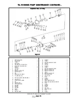
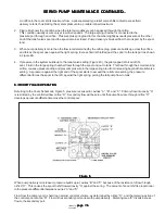
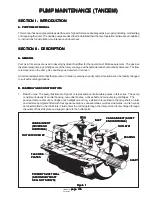
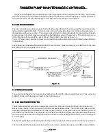
The pressure plate seals the pumping chamber as shown in Figure 3 on next page. A light spring holds the plate against
the cartridge until pressure builds up in the system. System pressure is effective against the area at the back of the plate,
which is larger than the area exposed to the pumping cartridge. Thus, an unbalanced force holds the plate against the
cartridge, sealing the cartridge and providing the proper running clearance for the rotor and vanes.
D. FLOW CONTROL AND RELIEF VALVE
D. FLOW CONTROL AND RELIEF VALVE
D. FLOW CONTROL AND RELIEF VALVE
D. FLOW CONTROL AND RELIEF VALVE
D. FLOW CONTROL AND RELIEF VALVE
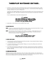
1. Maximum flow to the operating circuit and maximum system pressure are determined by the integral flow
control and relief valve in a special outlet cover used on some pumps. This feature is illustrated pictorially in Figures
4A,B, & C on next page.
Figure 3
Figure 3
Figure 3
Figure 3
Figure 3
SERVO PUMP MAINTENANCE CONTINUED...
SERVO PUMP MAINTENANCE CONTINUED...
SERVO PUMP MAINTENANCE CONTINUED...
SERVO PUMP MAINTENANCE CONTINUED...
SERVO PUMP MAINTENANCE CONTINUED...

