page 78
page 78
page 78
page 78
page 78
160B&C TM
800-00140
B. SHAFT ROTATION
B. SHAFT ROTATION
B. SHAFT ROTATION
B. SHAFT ROTATION
B. SHAFT ROTATION
Pumps are normally assembled for right-hand (clockwise) rotation as viewed from the shaft end. A pump made
for left-hand rotation is identified by an “L” in the model code.
NOTE:
NOTE:
NOTE:
NOTE:
NOTE: These pumps must be driven in the direction of the arrows cast on the pump ring. If it is desired to
change the direction of drive rotation, it is necessary to reverse the ring. (See Section VI-B-D and
Figure 10.)
CAUTION
CAUTION
CAUTION
CAUTION
CAUTION
Never drive a pump in the wrong direction of rotation.
Never drive a pump in the wrong direction of rotation.
Never drive a pump in the wrong direction of rotation.
Never drive a pump in the wrong direction of rotation.
Never drive a pump in the wrong direction of rotation.
Seizure may result, necessitating expensive repairs.
Seizure may result, necessitating expensive repairs.
Seizure may result, necessitating expensive repairs.
Seizure may result, necessitating expensive repairs.
Seizure may result, necessitating expensive repairs.
C. PIPING AND TUBING
C. PIPING AND TUBING
C. PIPING AND TUBING
C. PIPING AND TUBING
C. PIPING AND TUBING
1. All pipes and tubing must be thoroughly cleaned before installation. Recommended methods of cleaning
are sandblasting, wire brushing, and pickling.
2. To minimize flow resistance and the possibility of leakage, only as many fittings and connections as are
necessary for proper installation should be used.
3. The number of bends in tubing should be kept to a minimum to prevent excessive turbulence and friction
of oil flow. Tubing must not be bent too sharply. The recommended radius for bends is three times the
inside diameter of the tube.
D. OVERLOAD PROTECTION
D. OVERLOAD PROTECTION
D. OVERLOAD PROTECTION
D. OVERLOAD PROTECTION
D. OVERLOAD PROTECTION
A relief valve must be installed in the system, unless it is an integral part of the pump. The relief valve limits pressure
in the system to a prescribed maximum and protects the components from excessive pressure. The setting of the
relief valve depends on the work requirements of the system components.
E. PORT POSITIONS
E. PORT POSITIONS
E. PORT POSITIONS
E. PORT POSITIONS
E. PORT POSITIONS
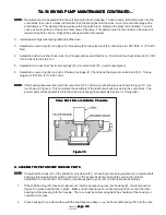
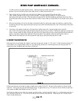
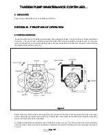
The pump cover can be assembled in four positions with respect to the body. A letter in the model code identifies
the cover position as shown in Figure 7.
Figure 7
Figure 7
Figure 7
Figure 7
Figure 7
Disassembly and assembly procedures are in Section VI-B and D.
SERVO PUMP MAINTENANCE CONTINUED...
SERVO PUMP MAINTENANCE CONTINUED...
SERVO PUMP MAINTENANCE CONTINUED...
SERVO PUMP MAINTENANCE CONTINUED...
SERVO PUMP MAINTENANCE CONTINUED...

