page 125
page 125
page 125
page 125
page 125
160B&C TM
800-00140
TYPICAL ADAPTOR PLATE
TYPICAL ADAPTOR PLATE
TYPICAL ADAPTOR PLATE
TYPICAL ADAPTOR PLATE
TYPICAL ADAPTOR PLATE
LET ENDS EXTEND BEYOND FLANGE
LET ENDS EXTEND BEYOND FLANGE
LET ENDS EXTEND BEYOND FLANGE
LET ENDS EXTEND BEYOND FLANGE
LET ENDS EXTEND BEYOND FLANGE
NOTE:
NOTE:
NOTE:
NOTE:
NOTE: Drive in direction of arrow.
8. To remove bearings from gear hubs, use gear puller or Arbor Press.
REASSEMBLY OF PUMP DRIVE
REASSEMBLY OF PUMP DRIVE
REASSEMBLY OF PUMP DRIVE
REASSEMBLY OF PUMP DRIVE
REASSEMBLY OF PUMP DRIVE
For reassembly, use the reverse procedure of 1 through 8.
NOTE:
NOTE:
NOTE:
NOTE:
NOTE: Plastic cord used for gasket material under pump adaptor plates and input housing is not reusable.
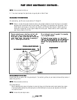
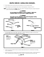
Replace with new material when reassembling. See Figure 3 for installation of cord gasket. Place
bolts should not be reused. Clean the old Locktite out of the bolt hole threads. Install new place
bolts with Locktite 262, on the engine adaptor and pump pad. Place bolts are used in pump drive
pad, torque studs to 150 ft. lbs..
Do not attempt to reuse this gasket. For assembly
Do not attempt to reuse this gasket. For assembly
Do not attempt to reuse this gasket. For assembly
Do not attempt to reuse this gasket. For assembly
Do not attempt to reuse this gasket. For assembly
use new gasket material.
use new gasket material.
use new gasket material.
use new gasket material.
use new gasket material.
On flywheel housings involving more than 4 bolt
On flywheel housings involving more than 4 bolt
On flywheel housings involving more than 4 bolt
On flywheel housings involving more than 4 bolt
On flywheel housings involving more than 4 bolt
holes, be sure cord gasket lap joint falls behind one
holes, be sure cord gasket lap joint falls behind one
holes, be sure cord gasket lap joint falls behind one
holes, be sure cord gasket lap joint falls behind one
holes, be sure cord gasket lap joint falls behind one
hole location which will be used for a bolt or stud
hole location which will be used for a bolt or stud
hole location which will be used for a bolt or stud
hole location which will be used for a bolt or stud
hole location which will be used for a bolt or stud
fastener. Do not lap ends behind an unused bolt
fastener. Do not lap ends behind an unused bolt
fastener. Do not lap ends behind an unused bolt
fastener. Do not lap ends behind an unused bolt
fastener. Do not lap ends behind an unused bolt
hole.
hole.
hole.
hole.
hole.
Remove protective paper strip from cord and with
Remove protective paper strip from cord and with
Remove protective paper strip from cord and with
Remove protective paper strip from cord and with
Remove protective paper strip from cord and with
adhesive side next to metal, install around pilot.
adhesive side next to metal, install around pilot.
adhesive side next to metal, install around pilot.
adhesive side next to metal, install around pilot.
adhesive side next to metal, install around pilot.
Cross ends, as shown, behind bolt hole and let ends
Cross ends, as shown, behind bolt hole and let ends
Cross ends, as shown, behind bolt hole and let ends
Cross ends, as shown, behind bolt hole and let ends
Cross ends, as shown, behind bolt hole and let ends
extend beyond flange. Use caution in assembly to
extend beyond flange. Use caution in assembly to
extend beyond flange. Use caution in assembly to
extend beyond flange. Use caution in assembly to
extend beyond flange. Use caution in assembly to
case, to prevent gasket dislocation.
case, to prevent gasket dislocation.
case, to prevent gasket dislocation.
case, to prevent gasket dislocation.
case, to prevent gasket dislocation.
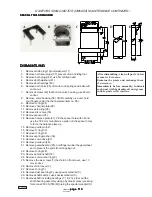
CORD GASKET
CORD GASKET
CORD GASKET
CORD GASKET
CORD GASKET
Figure 3
Figure 3
Figure 3
Figure 3
Figure 3
REPLACEMENT OF OIL SEAL
REPLACEMENT OF OIL SEAL
REPLACEMENT OF OIL SEAL
REPLACEMENT OF OIL SEAL
REPLACEMENT OF OIL SEAL
Install oil seal from engine side of engine adaptor. The rubber lip of the oil seal must point toward the inside of
pump drive gear box.
NOTE:
NOTE:
NOTE:
NOTE:
NOTE: Drive in direction of arrow.
Drive Plate Models:
When installing drive plate on flywheel, be sure the long end of the drive plate hub is toward the engine.
The hub should slide into the pilot bearing bore of the flywheel to ensure proper alignment of the drive
hub and drive shaft.
NOTE:
NOTE:
NOTE:
NOTE:
NOTE: Arrow indicates engine side.
PUMP DRIVE MAINTENANCE CONTINUED...
PUMP DRIVE MAINTENANCE CONTINUED...
PUMP DRIVE MAINTENANCE CONTINUED...
PUMP DRIVE MAINTENANCE CONTINUED...
PUMP DRIVE MAINTENANCE CONTINUED...

