background image

page 105

page 105

page 105

page 105

page 105

160B&C TM

800-00140

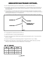
1

1A
1B
1C
1D
1E
1F
1G
1H
1I
1J

2
3

3A
3B

3C
3D
3E
3F
3G

5
6
9
11
12
13
14
20
24
25

1

1
1
1
1
1
1
1
1
1
3

1
1

1
6

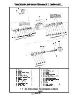
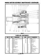
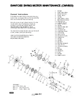
Hub-Spindle Sub-Assembly
Output Shaft
Seal
Bearing Cup
Bearing Cone
Bearing Cup
Bearing Cone
Hub
Spacer
Retaining Ring
Pipe Plug

Ring Gear
Carrier Assembly
Carrier
Thrust Washer

ITEM

ITEM

ITEM

ITEM

ITEM

QTY

QTY

QTY

QTY

QTY

DESCRIPTION

DESCRIPTION

DESCRIPTION

DESCRIPTION

DESCRIPTION

ITEM

ITEM

ITEM

ITEM

ITEM

QTY

QTY

QTY

QTY

QTY

DESCRIPTION

DESCRIPTION

DESCRIPTION

DESCRIPTION

DESCRIPTION

PARTS LIST FOR FIGURE 2

PARTS LIST FOR FIGURE 2

PARTS LIST FOR FIGURE 2

PARTS LIST FOR FIGURE 2

PARTS LIST FOR FIGURE 2

96
3
3
3
3

2
1
1
1
8
2
4
1
1
4

Needle Roller
Spacer
Planet Shaft
Planet Gear
Roll Pin

O-Ring
Cover
Input Gear
Thrust Washer
Bolt
Magnetic Pipe Plug
Shoulder Bolt
Retaining Ring
ID Plate
Drive Screw

Figure 2

Figure 2

Figure 2

Figure 2

Figure 2

SWING MOTOR GEARBOX MAINTENANCE CONTINUED...

SWING MOTOR GEARBOX MAINTENANCE CONTINUED...

SWING MOTOR GEARBOX MAINTENANCE CONTINUED...

SWING MOTOR GEARBOX MAINTENANCE CONTINUED...
SWING MOTOR GEARBOX MAINTENANCE CONTINUED...

Содержание Barko Loaders 160B

Страница 1: ...UAL SERVICE MANUAL SERVICE MANUAL 160B 160C and 200 Truck Mount 160B 160C and 200 Truck Mount 160B 160C and 200 Truck Mount 160B 160C and 200 Truck Mount 160B 160C and 200 Truck Mount includes slasher...

Страница 2: ...Motor Maintenance 100 Swing Motor Gearbox Maintenance S1C 103 Danfoss Swing Motor Maintenance OMV800 112 C Electrical System C Electrical System C Electrical System C Electrical System C Electrical Sy...

Страница 3: ...page 3 page 3 page 3 page 3 page 3 160B CTM 800 00140 Introduction Introduction Introduction Introduction Introduction...

Страница 4: ...by industrial accidents each year A professional operator should also be familiar with the information contained in other applicable sources such as American National Standards SAE OSHA etc ADDITIONAL...

Страница 5: ...ition Ignition Key Switch Key Switch Key Switch Key Switch Key Switch Power On Power On Power On Power On Power On Accessory Accessory Accessory Accessory Accessory Power Off Power Off Power Off Power...

Страница 6: ...IS 3 000 PSI MAXIMUM SWING ACCELERATION PRESSURE IS 3 000 PSI MAXIMUM SWING ACCELERATION PRESSURE IS 3 000 PSI MAXIMUM SWING BRAKING PRESSURE IS 2 000 PSI MAXIMUM SWING BRAKING PRESSURE IS 2 000 PSI M...

Страница 7: ...o BARKO within ten 10 days from the date on which the defect was discovered and any claim submitted within thirty 30 days after repair work is completed BARKO warranty does not cover 1 Defects damage...

Страница 8: ...be lowered to When machine is not operating or when leaving cab boom and attachment must be lowered to When machine is not operating or when leaving cab boom and attachment must be lowered to When mac...

Страница 9: ...on machine with lifted boom securely support on machine with lifted boom securely support machine and attachment machine and attachment machine and attachment machine and attachment machine and attac...

Страница 10: ...ubject to injury such off Riders on machine are subject to injury such off Riders on machine are subject to injury such as being struck by foreign objects and being as being struck by foreign objects...

Страница 11: ...cause Mechanically connected controls will cause Mechanically connected controls will cause movement of components at all times even if movement of components at all times even if movement of componen...

Страница 12: ...d exhaust standards meet noise and exhaust standards meet noise and exhaust standards meet noise and exhaust standards meet noise and exhaust standards WARNING WARNING WARNING WARNING WARNING Use caut...

Страница 13: ...EMBLY ASSEMBLY ASSEMBLY ASSEMBLY WARNING WARNING WARNING WARNING WARNING Boom is shown in lifted operating position Always shut down the machine and lower Boom is shown in lifted operating position Al...

Страница 14: ...ause a loose fit or too long Do not cut spacer blocks too short which will cause a loose fit or too long Do not cut spacer blocks too short which will cause a loose fit or too long which will cause fr...

Страница 15: ...NING WARNING WARNING Safe and stable mounting of this machine on Safe and stable mounting of this machine on Safe and stable mounting of this machine on Safe and stable mounting of this machine on Saf...

Страница 16: ...r hoses battery and other flammableparts Neverground arc welder or electrical accessories through turntable or boom bearings as arcing may occur causing bearing damage Always keep a fire extinguisher...

Страница 17: ...00140 Maintenance Maintenance Maintenance Maintenance Maintenance A PREVENTIVE MAINTENANCE A PREVENTIVE MAINTENANCE A PREVENTIVE MAINTENANCE A PREVENTIVE MAINTENANCE A PREVENTIVE MAINTENANCE Maintena...

Страница 18: ...void the warranty and may cause structural damage and injury damage and injury damage and injury damage and injury damage and injury WARNING WARNING WARNING WARNING WARNING Do not support the machine...

Страница 19: ...lways needed for Safety glasses or goggles are always needed for Safety glasses or goggles are always needed for eye protection from electric arcs from shorts or eye protection from electric arcs from...

Страница 20: ...raulic Oil Reservoir Hydraulic Oil Reservoir Hydraulic Oil Reservoir On new machines the oil must be changed after the first 50 hours and then every 1000 hours after that Hydraulic Oil Filter Hydrauli...

Страница 21: ...LY WEEKLY WEEKLY MONTHLY MONTHLY MONTHLY MONTHLY MONTHLY 6 MONTHS 6 MONTHS 6 MONTHS 6 MONTHS 6 MONTHS 2 MONTHS 2 MONTHS 2 MONTHS 2 MONTHS 2 MONTHS Pump Drive Pump Drive Pump Drive Pump Drive Pump Driv...

Страница 22: ...ee service manual for more information WARNING WARNING WARNING WARNING WARNING Boom is shown in lifted operating position Always lower boom and Boom is shown in lifted operating position Always lower...

Страница 23: ...grease with a lithium base EP additives and rust inhibitors Above 32 degrees F Use 2 grease Below 32 degrees F Use 1 grease Theselubepoints TurntableBearingand Swing Motor Pinion can be greased from...

Страница 24: ...container and store in a protected area Water and sediment must be removed before fuel gets to the engine Do not use de icers to remove water from fuel Do not depend on fuel filters to remove water N...

Страница 25: ...rade Grade 68 46 32 F to 45 F ABOVE 45 F o Below 32 F ambient consult the factory Below 32 F ambient consult the factory Below 32 F ambient consult the factory Below 32 F ambient consult the factory B...

Страница 26: ...G BOLT SWING MOTOR BOLT AND SWING MOTOR GEARBOX BOLT TORQUE GEARBOX BOLT TORQUE GEARBOX BOLT TORQUE GEARBOX BOLT TORQUE GEARBOX BOLT TORQUE The Turntable Bearing Bolts should be checked and retorqued...

Страница 27: ...E BEAM THAT SUBFRAME BEAM THAT SUBFRAME BEAM THAT SUBFRAME BEAM THAT SUBFRAME ISMOUNTEDTO ISMOUNTEDTO ISMOUNTEDTO ISMOUNTEDTO ISMOUNTEDTO BOTTOM CLAMP PLATE BOTTOM CLAMP PLATE BOTTOM CLAMP PLATE BOTTO...

Страница 28: ...RADIAL MIN 8 RADIAL MIN 8 RADIAL MIN 8 RADIAL MARKS ON MARKS ON MARKS ON MARKS ON MARKS ON HEAD GRADE 9 HEAD GRADE 9 HEAD GRADE 9 HEAD GRADE 9 HEAD GRADE 9 BOW MALLOY BOW MALLOY BOW MALLOY BOW MALLOY...

Страница 29: ...page 29 page 29 page 29 page 29 160B CTM 800 00140 Maintenance Maintenance Maintenance Maintenance Maintenance B HYDRAULIC SYSTEM B HYDRAULIC SYSTEM B HYDRAULIC SYSTEM B HYDRAULIC SYSTEM B HYDRAULIC...

Страница 30: ...page 30 page 30 page 30 page 30 page 30 160B CTM 800 00140 HYDRAULIC SCHEMATICS HYDRAULIC SCHEMATICS HYDRAULIC SCHEMATICS HYDRAULIC SCHEMATICS HYDRAULIC SCHEMATICS...

Страница 31: ...0 HYDRAULIC SCHEMATICS CONTINUED HYDRAULIC SCHEMATICS CONTINUED HYDRAULIC SCHEMATICS CONTINUED HYDRAULIC SCHEMATICS CONTINUED HYDRAULIC SCHEMATICS CONTINUED SLASHER APPLICATION SLASHER APPLICATION SLA...

Страница 32: ...rty to life limb and property to life limb and property to life limb and property Altering the settings on a new machine will void Altering the settings on a new machine will void Altering the setting...

Страница 33: ...NGE NOT CHANGE NOT CHANGE NOT CHANGE FROM 2000 PSI FROM 2000 PSI FROM 2000 PSI FROM 2000 PSI FROM 2000 PSI Controlsbraking pressure and is factory set at 2000 PSI Figure 2 Figure 2 Figure 2 Figure 2 F...

Страница 34: ...d replace cap remove relief cap make adjustment and replace cap d If adjusting makes no difference remove both accelerating and braking pressure reliefs check o rings then switch reliefs from top to b...

Страница 35: ...PRELIEF PUMPRELIEF PUMPRELIEF PUMPRELIEF VALVES VALVES VALVES VALVES VALVES Relief Relief Relief Relief Relief Valves Valves Valves Valves Valves Pump Pump Pump Pump Pump Valve Valve Valve Valve Valve...

Страница 36: ...hydraulic system keep hydraulic system keep all all all all all parts clean and parts clean and parts clean and parts clean and parts clean and remove remove remove remove remove all dirt from the all...

Страница 37: ...RVOIR FILLINGTHERESERVOIR FILLINGTHERESERVOIR FILLINGTHERESERVOIR 1 With drain plug in place and tightened refill reservoir with recommended hydraulic oil Be sure filler cap screen is in place and cle...

Страница 38: ...ASS BYPASS BOLTS BOLTS BOLTS BOLTS BOLTS O RING O RING O RING O RING O RING FILTER FILTER FILTER FILTER FILTER ELEMENT ELEMENT ELEMENT ELEMENT ELEMENT Figure 2 Figure 2 Figure 2 Figure 2 Figure 2 THE...

Страница 39: ...mospheric pressure air may be drawn in where fluid will not necessarily leak out 5 Fluid level too low This can cause vortexing at pump inlet in reservoir thus drawing in air 6 Air trapped in filter w...

Страница 40: ...nings keep dirt out of tubelines and openings keep dirt out of tubelines and openings keep dirt out of tubelines and openings PIPE THREAD SEALER PIPE THREAD SEALER PIPE THREAD SEALER PIPE THREAD SEALE...

Страница 41: ...item 8 Heating item 10 7 and the stiff portion of 1 in a 200 oven for 5 minutes will make it more pliable Some kits may contain extra seals When installing the wear rings items 2 6 put the cuts on opp...

Страница 42: ...1 1 10 10 10 10 10 MODULAR BACKUP RING MODULAR BACKUP RING MODULAR BACKUP RING MODULAR BACKUP RING MODULAR BACKUP RING 1 1 1 1 1 11 11 11 11 11 O RING O RING O RING O RING O RING 1 1 1 1 1 1 1 1 1 1 3...

Страница 43: ...s manual on collector parts list Port numbers are stamped into collector for easy reference HYDRAULIC COLLECTOR SEAL KIT INSTRUCTIONS HYDRAULIC COLLECTOR SEAL KIT INSTRUCTIONS HYDRAULIC COLLECTOR SEAL...

Страница 44: ...operly for installation Heat teflon rings to 200 400 degrees Fahrenheit WARNING WARNING WARNING WARNING WARNING Do not heat teflon rings beyond 400 degrees Fahrenheit Do not heat teflon rings beyond 4...

Страница 45: ...rocedure It should be followed very closely to ensure that the valve bank is properly reassembled after repairs have been made See Figure 1 Figure 1 Figure 1 Figure 1 Figure 1 Figure 1 A Take a waterp...

Страница 46: ...rviced Next poppet sleeve Item 17 Figure 3 4 unless it is to be serviced Next poppet sleeve Item 17 Figure 3 4 unless it is to be serviced Next poppet sleeve Item 17 Figure 3 4 unless it is to be serv...

Страница 47: ...tbehandledcarefullytoavoiddamage Placethespoolinasoftjawedviseandremovethestripperbolt Item 14 withawrench Cautiousapplicationofheatmayberequiredtofreethestripperboltbecauseananaerobicthreadadhesive i...

Страница 48: ...eries Section Component Parts See Figure 3 4 4 Back Cap Screw 2 5 Back Cap 1 6 RetainerPlate 3 7 Backup Ring 2 8 Spool Seal 2 9 Retainer Plate Screw 2 10 CheckValveCap 1 OrValveCap F I N 1 11 O RingSe...

Страница 49: ...ring face of the valve housing extends across the o ring face of the valve housing extends across the o ring face of the valve housing extends across the o ring face of the valve housing It should no...

Страница 50: ...prepare parts properly may result in assembly failure prepare parts properly may result in assembly failure prepare parts properly may result in assembly failure Then lightly coat the detent balls It...

Страница 51: ...ue them to 80 90 ft lbs ITEM ITEM ITEM ITEM ITEM DESCRIPTION DESCRIPTION DESCRIPTION DESCRIPTION DESCRIPTION QTY QTY QTY QTY QTY 1 O RING 2 2 O RING 1 3 BACKUPRING 1 4 GASKET WASHER 1 Figure 5 Figure...

Страница 52: ...d to the threads Use heat carefully to avoid warping spool PREPARATIONOFPARTS PREPARATIONOFPARTS PREPARATIONOFPARTS PREPARATIONOFPARTS PREPARATIONOFPARTS 1 Clean adhesive from threads of spool strippe...

Страница 53: ...ar in size Be sure to insert seals Seals are similar in size Be sure to insert seals 1 10 in their proper position They are not 1 10 in their proper position They are not 1 10 in their proper position...

Страница 54: ...acepoppet No motion slow or erratic system operation Worn pump Defectivecylinderormotor Lowreservoiroillevel Clogged suction strainer Suction line restricted Reliefvalvenotproperlyset Relief valve pop...

Страница 55: ...each basic model series are covered in the model code SECTION II DESCRIPTION SECTION II DESCRIPTION SECTION II DESCRIPTION SECTION II DESCRIPTION SECTION II DESCRIPTION A GENERAL A GENERAL A GENERAL...

Страница 56: ...otion of the piston reverses and fluid is pushed out of the cylinder block into the outlet port B GEROTOR PUMP B GEROTOR PUMP B GEROTOR PUMP B GEROTOR PUMP B GEROTOR PUMP A gerotor pump is composed of...

Страница 57: ...alled in couplings with a slip fit Pounding can injure couplings with a slip fit Pounding can injure couplings with a slip fit Pounding can injure couplings with a slip fit Pounding can injure couplin...

Страница 58: ...a hydraulic system and careful selection of it should be made with the assistance of a reputable supplier Proper selection of oil assures satisfactory life and operation of system components with part...

Страница 59: ...valves pressure relief is obtained by spinning the wheels SECTION V SERVICE AND MAINTENANCE SECTION V SERVICE AND MAINTENANCE SECTION V SERVICE AND MAINTENANCE SECTION V SERVICE AND MAINTENANCE SECTIO...

Страница 60: ...d is the best insurance for long service life Therefore the reservoir should be checked periodically for dirt or other contaminants Contamination level should not exceed three 3 milligrams 100 millili...

Страница 61: ...ation or wear of the pump or other hydraulic units Therefore the use of cloth to strain the fluid should be avoided to prevent lint from getting into the system D ADJUSTMENTS D ADJUSTMENTS D ADJUSTMEN...

Страница 62: ...leaks Checksuperchargepump function Be certain correct type of oil is used for refilling or adding to system Run hydraulic system until unit is warm to the touch and noise disappears If established th...

Страница 63: ...en working on a Absolute cleanliness is essential when working on a Absolute cleanliness is essential when working on a Absolute cleanliness is essential when working on a Absolute cleanliness is esse...

Страница 64: ...INGRING 1 21 WASHER 1 22 SPRING 1 23 WASHER 1 24 SHAFT 1 25 SCREW 4 26 PINTLECOVER 1 27 SHIMKIT 1 28 O RING 1 29 PINTLEBEARINGSPACER 1 30 SCREW 4 31 COVER 1 32 SHIMKIT 1 33 O RING 1 34 PINTLEBEARINGSP...

Страница 65: ...ered roller bearing 10 from the end of shaft 24 3 Removewaferplate 11 fromvalveblock 51 thenremovepin 12 fromvalveblock 4 Slide bearing spacer 13 off shaft 24 5 Remove rotating group parts 14 through...

Страница 66: ...ont bearing for scuffing peeling or spalling of the rollers and or roughness when turned in the race DO NOT DO NOT DO NOT DO NOT DO NOT disassemble the yoke pintle bearing if the yoke and shaft bearin...

Страница 67: ...oval Front Bearing Removal Front Bearing Removal Figure 9 Figure 9 Figure 9 Figure 9 Figure 9 F INSPECTIONREPAIRANDREPLACEMENT F INSPECTIONREPAIRANDREPLACEMENT F INSPECTIONREPAIRANDREPLACEMENT F INSPE...

Страница 68: ...17 Inspect the valve block parts as follows a Inspect the threaded plugs for worn corners on the hex head stripped threads and burrs in the o ring groove Use an India stone to remove burrs if threads...

Страница 69: ...s into the valve block The gerotor parts will be assembled into the valve block during final assembly Section VI Paragraph I H ASSEMBLY OF PISTON PUMP HOUSING PARTS H ASSEMBLY OF PISTON PUMP HOUSING P...

Страница 70: ...NOTE If the calculated shim thickness is greater than 0 020 another shim must be added to the opposite side of the yoke to reduce the total shim thickness to less than 0 020 inch Shim thickness at eit...

Страница 71: ...tightening 10 Use a feeler gauge to measure the opening between valve block 51 and housing 8 Four measurements should be obtained equidistant around the unit A tapered feeler gauge is especially usef...

Страница 72: ...PUMP VALVE BLOCK AND GEROTOR PUMP 1 Assemble wafer plate locating pin 12 into valve block 51 Refer to Figure 8 2 Assemble wafer plate 11 over the bearing race and locating pin 12 with bronze surface a...

Страница 73: ...dustrialequipment Thepositive displacementpumpingcartridgesaretherotaryvanetypewithshaftsideloadshydraulicallybalanced Theflowratedepends on the pump size and the speed at which it is driven All units...

Страница 74: ...sonnel should be consulted SECTION III PRINCIPLES OF OPERATION SECTION III PRINCIPLES OF OPERATION SECTION III PRINCIPLES OF OPERATION SECTION III PRINCIPLES OF OPERATION SECTION III PRINCIPLES OF OPE...

Страница 75: ...f the plate which is larger than the area exposed to the pumping cartridge Thus an unbalanced force holds the plate against the cartridge sealing the cartridge and providing the proper running clearan...

Страница 76: ...from increasing beyond the relief valve setting As pressure against the right end of the spool starts to exceed the relief valve setting the pressure differential forces the spool to the left against...

Страница 77: ...ECTIONS A DRIVECONNECTIONS A DRIVECONNECTIONS A DRIVECONNECTIONS CAUTION CAUTION CAUTION CAUTION CAUTION Pump shafts are designed to be installed in couplings Pump shafts are designed to be installed...

Страница 78: ...and tubing must be thoroughly cleaned before installation Recommended methods of cleaning are sandblasting wire brushing and pickling 2 To minimize flow resistance and the possibility of leakage only...

Страница 79: ...isy and or erratic operation 2 Clean fluid is the best insurance for long service life Therefore the reservoir should be checked periodically for dirt or other contaminants If the fluid becomes contam...

Страница 80: ...ll vertical cylinders discharge released Lower all vertical cylinders discharge released Lower all vertical cylinders discharge released Lower all vertical cylinders discharge released Lower all verti...

Страница 81: ...81 page 81 page 81 page 81 160B CTM 800 00140 SERVO PUMP MAINTENANCE CONTINUED SERVO PUMP MAINTENANCE CONTINUED SERVO PUMP MAINTENANCE CONTINUED SERVO PUMP MAINTENANCE CONTINUED SERVO PUMP MAINTENANC...

Страница 82: ...ith pipe thread plugs only and slide the priority valve spool from the cover If the snap ring exists remove it from the cover Disassemble the relief valve by removing the plug spring poppet and shims...

Страница 83: ...ll sharp edges on the parts of a new cartridges kit should be stoned prior to installation 1 Assembly of Flow Control Cover See Figure 8 Assemble the snap ring in place within the bore early design on...

Страница 84: ...ints in the direction of rotation Check the assembly against Figure 10 Install the rotor on the shaft and insert the vanes in the rotor slots Be certain the radius edges of the vanes are toward the ca...

Страница 85: ...ve to its bore and check for stickiness A gritty feeling on valve periphery can be polished with crocus cloth Do not remove excess material round off edges of lands or try to polish bore Wash all part...

Страница 86: ...B ASSEMBLY AND CONSTRUCTION 1 Basic Pumps The pump illustrated in Figure 1 is representative of all double pumps in this series The pump consists principally of an inlet housing two outlet bodies a d...

Страница 87: ...the rotor turns centrifugalforceonthevanes aidedbyunder vanepressurefedfromtheoutletport causesthevanestofollow the elliptical inner surface of the ring Figure 2 Figure 2 Figure 2 Figure 2 Figure 2 Ra...

Страница 88: ...r slot holding the vane tip against the cam ring Figure 3 Figure 3 Figure 3 Figure 3 Figure 3 C HYDRAULIC BALANCE C HYDRAULIC BALANCE C HYDRAULIC BALANCE C HYDRAULIC BALANCE C HYDRAULIC BALANCE The pu...

Страница 89: ...is pressed into the body SECTION IV INSTALLATION AND OPERATING INSTRUCTIONS SECTION IV INSTALLATION AND OPERATING INSTRUCTIONS SECTION IV INSTALLATION AND OPERATING INSTRUCTIONS SECTION IV INSTALLATI...

Страница 90: ...iewed from the shaft end A pump made for left hand rotation is identified by an L in the model code NOTE NOTE NOTE NOTE NOTE If it is desired to reverse the direction of drive rotation it is necessary...

Страница 91: ...ide of the pump to purge entrapped air No Load Starting These pumps are designed to start up with no load on the pressure ports They should never be started against a load or a closed center valve SEC...

Страница 92: ...he reservoir can ruin the pump and other components If bubbles are seen locate the source of the air and seal the leak See Table 1 5 A pump which is running excessively hot or noisy is a potential fai...

Страница 93: ...em Add new filtered fluid of proper viscosity Check inlet connections to determine where air is being drawn in Tighten any loose connections See that fluid in reservoirisaboveintakepipeopening Check m...

Страница 94: ...ap all lines to pressure Plug all removed units and cap all lines to prevent the entry of dirt into the system prevent the entry of dirt into the system prevent the entry of dirt into the system preve...

Страница 95: ...et Body Outlet Body Outlet Body 1 1 1 1 1 16 16 16 16 16 Back up Ring Back up Ring Back up Ring Back up Ring Back up Ring 1 1 1 1 1 17 17 17 17 17 O Ring O Ring O Ring O Ring O Ring 1 1 1 1 1 18 18 18...

Страница 96: ...0 from the inlet support plate unless they are damaged The pins are of a drive loc type and can be difficult to remove C INSPECTION AND REPAIR C INSPECTION AND REPAIR C INSPECTION AND REPAIR C INSPECT...

Страница 97: ...T IMPORTANT IMPORTANT IMPORTANT IMPORTANT During handling and shipping of precision machined cartridge parts it is possible to raise burrs on the sharp edges All sharp edges of new cartridge kit shoul...

Страница 98: ...tightening CoverEnd 25 Shaft End 35 j Check rotor 28 for bind by inserting the index finger through the shaft ope t ope t ope t ope t opening of inlet support plate 21 Hold the cartridge kit in a hor...

Страница 99: ...ing Turn the inlet housing slightly until the alignment marks are in line and the large screw holes are aligned Oil and install four screws 5 and torque tighten to 140 160 lb ft j Turn pump shaft by h...

Страница 100: ...can be ordered Holding tool for bushing can be ordered Bushing for 1 1 4 DIA can be ordered DISASSEMBLY DISASSEMBLY DISASSEMBLY DISASSEMBLY DISASSEMBLY REFER TO FIGURE 1 REFER TO FIGURE 1 REFER TO FI...

Страница 101: ...EASSEMBLY REASSEMBLY 1 Place motor housing in main holding tool with flange uppermost Grease check valves item 11 check valves must have new o rings and place them in the borings with a light blow fro...

Страница 102: ...xagon socket install the seven washers and screws items 18 and 19 Torque to 460 500 in lbs 5 2 5 7 daNm 19 Using a 9 16 hexagon socket install drain plug item 22 Torque to 265 530 in lbs 3 6 daNm 20 I...

Страница 103: ...e disassembly and after assembly to make sure that the unit sgearsandsealantsareworkingproperly Thefollowinginformationbrieflyoutlineswhattolookforwhenperforming these tests THE ROLL TEST THE ROLL TES...

Страница 104: ...hes 1 02 inches 1 02 inches 1 02 inches 1 02 inches Maximum Maximum Maximum Maximum Maximum 65 inches 65 inches 65 inches 65 inches 65 inches Figure 1 Figure 1 Figure 1 Figure 1 Figure 1 TIGHTENINGAND...

Страница 105: ...ITEM ITEM ITEM QTY QTY QTY QTY QTY DESCRIPTION DESCRIPTION DESCRIPTION DESCRIPTION DESCRIPTION PARTS LIST FOR FIGURE 2 PARTS LIST FOR FIGURE 2 PARTS LIST FOR FIGURE 2 PARTS LIST FOR FIGURE 2 PARTS LIS...

Страница 106: ...t with bearing cone 1D and seal 1B attached If so remove seal 1B from output shaft and discard Use a soft punch and hammer to remove bearing cone 1D from the shaft Be very careful not to strike the sh...

Страница 107: ...remaining planet gears 13 At this point the carrier sub assembly is complete HUB SHAFT SUB ASSEMBLY HUB SHAFT SUB ASSEMBLY HUB SHAFT SUB ASSEMBLY HUB SHAFT SUB ASSEMBLY HUB SHAFT SUB ASSEMBLY 1 Oil ou...

Страница 108: ...es continue to do steps D through H D Place a bearing cone pressing tool T 116407 on top of retaining ring 1I E Press fixture with a hydraulic ram or by striking it with soft face hammer Pressure shou...

Страница 109: ...ake sure that the shoulder bolt hole that is marked with an X on the ring gear aligns with any one of the marked shoulder bolt holes on the hub The X should be on the cover side of the ring gear 8 Sta...

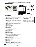
Страница 110: ...s unit The tool diagrams included in this manual are intended for the customer who may wish to have a tool made All tools exist as one piece and must be made from mild steel All dimensions are given i...

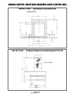
Страница 111: ...1E TOOL NO T 116412 Bearing Cup Pressing Fixture used with bearing cups 1C and 1E TOOL NO T 116402 Seal Pressing Fixture used with seal 1B TOOL NO T 116402 Seal Pressing Fixture used with seal 1B TOOL...

Страница 112: ...MAKE SURE YOU DISASSEMBLE AND ASSEMBLE YOUR HYDRAULIC EQUIPMENT IN A CLEAN AREA It is important to airblast all parts and wipe them with a clean lintless cloth before assembly USECAUTIONINGRIPPINGALL...

Страница 113: ...8 lift off carefully as a unit hold your fingers under the channel plate item no 28 9 RemoveO ring 24 10 Remove channel plate 28 11 Remove stop ring 29 12 Remove disc valve 30 13 Removespacer 35 14 Re...

Страница 114: ...of the gearwheel set at the point where the tip of a spline tooth is opposite the bottom of a tooth in the external rotor teeth see drawing 11 Replace valve drive 27 mark the bottom of a spline tooth...

Страница 115: ...e 115 page 115 page 115 page 115 160B CTM 800 00140 Maintenance Maintenance Maintenance Maintenance Maintenance C ELECTRICAL SYSTEM C ELECTRICAL SYSTEM C ELECTRICAL SYSTEM C ELECTRICAL SYSTEM C ELECTR...

Страница 116: ...E USING AN EXTRA BATTERY TO START MACHINE USING AN EXTRA BATTERY TO START MACHINE If necessary to use an extra battery and jumper cables to start engine be careful This is a two person operation There...

Страница 117: ...iate medical attention acid contact wash immediately with water and seek immediate medical attention acid contact wash immediately with water and seek immediate medical attention acid contact wash imm...

Страница 118: ...chine operation Adjusting Belt Tension Adjusting Belt Tension Adjusting Belt Tension Adjusting Belt Tension Adjusting Belt Tension 1 2 of movement 1 2 of movement 1 2 of movement 1 2 of movement 1 2 o...

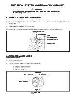
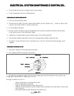
Страница 119: ...ULATOR CHECKINGTHEREGULATOR CHECKINGTHEREGULATOR CHECKINGTHEREGULATOR 1 Use steps 1 through 5 of Checking Alternator Output 2 Put a small screwdriver in test hole See Figure 3 Alternator Alternator Al...

Страница 120: ...The ground connection is not making a good contact 5 Thealternatorisdamaged 6 The engine is locked 7 The starter has damage 8 The wiring or the solenoid is damaged ELECTRICAL SYSTEM TROUBLE SHOOTING E...

Страница 121: ...21 page 121 page 121 160B CTM 800 00140 Maintenance Maintenance Maintenance Maintenance Maintenance D POWER UNIT MAINTENANCE D POWER UNIT MAINTENANCE D POWER UNIT MAINTENANCE D POWER UNIT MAINTENANCE...

Страница 122: ...ecifications operating instructions and maintenance and lubrication information will be found in the Cummins GM or John Deere engine manual which accompanies the machine Either of these manuals may al...

Страница 123: ...mended that the fluid level be checked daily at the same time checking for fluid leaks Because the lubricant system is the heart of the unit it is especially important that the fluid be kept clean The...

Страница 124: ...t of oil seal be required drive oil seal toward engine side of engine adaptor 1 1 1 1 1 ENGINE ENGINE ENGINE ENGINE ENGINE 2 2 2 2 2 FLYWHEELCOVER FLYWHEELCOVER FLYWHEELCOVER FLYWHEELCOVER FLYWHEELCOV...

Страница 125: ...which will be used for a bolt or stud fastener Do not lap ends behind an unused bolt fastener Do not lap ends behind an unused bolt fastener Do not lap ends behind an unused bolt fastener Do not lap e...

Страница 126: ...of a Pump Drive with a Disconnect Clutch Example of a Pump Drive with a Disconnect Clutch Example of a Pump Drive with a Disconnect Clutch Example of a Pump Drive with a Disconnect Clutch HAND HOLE PL...

Страница 127: ...he machine is working See Figure 1 NOTE NOTE NOTE NOTE NOTE This is especially important in the fall months as the trees shed their leaves AIRCLEANERBONNET AIRCLEANERBONNET AIRCLEANERBONNET AIRCLEANER...

Страница 128: ...r intake Replace the element only when the restriction has reached the maximum allowed by the engine manufacturer Contact the Barko Service Department for maximum values and any other questions concer...

Страница 129: ...PRESS YOUR PRESS YOUR FRESH GASKET FRESH GASKET FRESH GASKET FRESH GASKET FRESH GASKET TO SEE IF IT TO SEE IF IT TO SEE IF IT TO SEE IF IT TO SEE IF IT SPRINGS BACK SPRINGS BACK SPRINGS BACK SPRINGS B...

Страница 130: ...t in is to be sure nothing gets in THE IMPORTANT DON TS TO ALWAYS REMEMBER THE IMPORTANT DON TS TO ALWAYS REMEMBER THE IMPORTANT DON TS TO ALWAYS REMEMBER THE IMPORTANT DON TS TO ALWAYS REMEMBER THE I...

Страница 131: ...UNT FRONTMOUNT FRONTMOUNT REARMOUNT REARMOUNT REARMOUNT REARMOUNT REARMOUNT Side View of Engine Side View of Engine Side View of Engine Side View of Engine Side View of Engine see detail Figure 2 see...

Страница 132: ...CTM 800 00140 Maintenance Maintenance Maintenance Maintenance Maintenance E GRAPPLE SERVICE AND E GRAPPLE SERVICE AND E GRAPPLE SERVICE AND E GRAPPLE SERVICE AND E GRAPPLE SERVICE AND INSTALLATION IN...

Страница 133: ...re that manifold plate and rotate stop 280 degree rotators only are positioned away from loader as shown in Figure 4 NOTE NOTE NOTE NOTE NOTE The 280 degree grapple uses a vane motor which along with...

Страница 134: ...nd grapple open and close function Watch for hydraulic oil leaks If functions perform according to instructions on levers connections have been properly made 2 Position loader so that end of boom can...

Страница 135: ...death severe injury or Loose or overtorqued bolts can cause death severe injury or Loose or overtorqued bolts can cause death severe injury or Loose or overtorqued bolts can cause death severe injury...

Страница 136: ...th lip facing proper direction IMPORTANT IMPORTANT IMPORTANT IMPORTANT IMPORTANT Note direction that u cup seal faces before removing old seal Be sure to install new Note direction that u cup seal fac...

Страница 137: ...y Repack cylinder Repack collector shaft Check oil flow from loader and adjust properly Consult loader manufacturer Replace cartridge Check oil flow from loader and adjust properly Consult loader manu...

Страница 138: ...page 138 page 138 page 138 page 138 page 138 160B CTM 800 00140 Trouble Shooting Trouble Shooting Trouble Shooting Trouble Shooting Trouble Shooting...

Страница 139: ...ngine oil and fill with heavierweightengineoil Engineoverheats Lowcoolantlevel Loose worn or broken fan belt Radiatorplugged Air filter elements plugged Fill to correct level and check for leaks Tight...

Страница 140: ...r dirty Reliefvalveimproperlyadjusted Incorrect hydraulic oil viscosity Excessive load Pump not receiving hydraulic oil Damagedline Any or all of the following Replace dirty filters Clogged inlet line...

Страница 141: ...ed connection Loose alternator belts Clean and tighten battery connections Tighten or replace belts Starter will not work or cranks slowly Loose or corroded connections Wrong engine oil Clean and tigh...

Страница 142: ...No steering control if applicable Leakage or blockage in hydraulic system Carrier system not operational Repair or replace sources of leaks and blocks Repair or replace as needed Machine steering in o...

Страница 143: ...e any decals listed or shown here for application on any Barko machine The decals for application on any Barko machine The decals for application on any Barko machine The decals for application on any...

Страница 144: ...f any kind and shut down machine when not operating or before maintenance of any kind and shut down machine when not operating or before maintenance of any kind and shut down machine when not operatin...

Страница 145: ...00883 DANGER ImproperElectricalConnections 1 3 539 00884 CAUTION Hydraulic Oil Only 1 4 539 00885 WARNING RotatingCoolerFan 2 5 539 00886 WARNING Combustible Flammable Fluids 1 6 539 00887 CAUTION Die...

Страница 146: ...aux kits 3 4 98 after 1 32 281 00063 WARNING Excessive Hydraulic Pressure 1 33 281 00065 WARNING Loose or Overtorqued Bolt Hazard deleted8 7 96 1 replaced by 539 00881 in base kit 34 281 00076 DECAL...

Отзывы:

Похожие инструкции для Barko Loaders 160B