page 94
page 94
page 94
page 94
page 94
160B&C TM
800-00140
It should always be remembered that many apparent pump failures are actually due to the failure of other parts of
the system. The cause of improper operation is best diagnosed with adequate testing equipment and a thorough
understanding of the complete hydraulic system.
SECTION VI - OVERHAUL
SECTION VI - OVERHAUL
SECTION VI - OVERHAUL
SECTION VI - OVERHAUL
SECTION VI - OVERHAUL
A. GENERAL
A. GENERAL
A. GENERAL
A. GENERAL
A. GENERAL
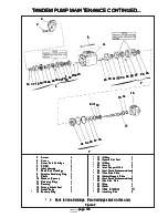
During disassembly, pay particular attention to identification of the parts, especially the cartridges, for correct
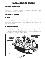
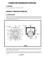
assembly. Figure 7 on next page is an exploded view which shows the proper relationship of parts for disassembly
and assembly. Refer to Figure 1 and Figure 7 for the correct assembled relationship of the parts.
WARNING
WARNING
WARNING
WARNING
WARNING
Before breaking a circuit connection, make certain
Before breaking a circuit connection, make certain
Before breaking a circuit connection, make certain
Before breaking a circuit connection, make certain
Before breaking a circuit connection, make certain
that power is off and system pressure has been released.
that power is off and system pressure has been released.
that power is off and system pressure has been released.
that power is off and system pressure has been released.
that power is off and system pressure has been released.
Lower all vertical cylinders, discharge accumulators
Lower all vertical cylinders, discharge accumulators
Lower all vertical cylinders, discharge accumulators
Lower all vertical cylinders, discharge accumulators
Lower all vertical cylinders, discharge accumulators
and block any load whose movement could generate
and block any load whose movement could generate
and block any load whose movement could generate
and block any load whose movement could generate
and block any load whose movement could generate
pressure. Plug all removed units and cap all lines to
pressure. Plug all removed units and cap all lines to
pressure. Plug all removed units and cap all lines to
pressure. Plug all removed units and cap all lines to
pressure. Plug all removed units and cap all lines to
prevent the entry of dirt into the system.
prevent the entry of dirt into the system.
prevent the entry of dirt into the system.
prevent the entry of dirt into the system.
prevent the entry of dirt into the system.
B. DISASSEMBLY
B. DISASSEMBLY
B. DISASSEMBLY
B. DISASSEMBLY
B. DISASSEMBLY
1. Basic Pump: Remove the foot mounting and shaft key (1) if used. Support the pump on blocks or clamp the
body in a vise. If a vise is used, use protective jaws to avoid damage to outlet body (15) and its machined
surfaces. Mark the pump inlet, outlet and cover for correct reassembly. Remove the four cover screws (2)
and lift cover (3) from the pump. This will expose the cover end cartridge (4). Discard square cut
seal (18) and o-ring (19).
2. Pull or pry cover cartridge (4) from the inlet housing. Set aside for disassembly during step B8.
3. Remove four screws (5) from the inlet housing (6). Separate inlet housing (6) and outlet body (15). This
exposes shaft end cartridge (7). Discard square cut seal (18) and o-ring (19). Refer to Figure 7.
4. Rotate shaft to loosen cartridge (7), then remove the cartridge from outlet body (15). Set aside for disassembly
during step B8.
5. Remove spirolox ring (8). Slide shaft (9) and bearing (12) from outlet body (15).
6. If bearing (12) is defective, remove retaining ring (11) and press bearing from the shaft with an arbor press.
(Apply force to inner race of bearing).
NOTE:
NOTE:
NOTE:
NOTE:
NOTE: In the following step, secondary shaft seal (13) is used on double shaft seal models only and will not exist
on standard units.
7. Remove spacer (10) from the outlet body, then drive shaft seal (13) and (14) from the outlet body (15). Be
careful not to damage the bore areas where the seals were located.
8. Disassemble the two cartridge kits one at a time. Follow the procedure noted in this step. Keep the parts
separated from each other during inspection, repair, and assembly.
a. Remove o-ring (17), back-up ring (16) and square sealing ring (18) from the outlet support plate.
b. Scribe a line across the outer surface of the cartridge kit. The scribe marking will provide a
reference for parts during assembl
TANDEM PUMP MAINTENANCE CONTINUED...
TANDEM PUMP MAINTENANCE CONTINUED...
TANDEM PUMP MAINTENANCE CONTINUED...
TANDEM PUMP MAINTENANCE CONTINUED...
TANDEM PUMP MAINTENANCE CONTINUED...

