leakage during backpressure testing.
(i) Cover Plate, inlet and outlet joints.
(ii) All tube fittings and connections.
(iii) Possible point of leakage on the pilot valve.
11. Repair of valves which show leaks in backpressure
testing may be attempted by tightening the joint
involved to normal tightness, while the valve is in
the testing area. The valve is to be examined for
cause of failure, the cause corrected, and the
test repeated.
E. Conversions between Conventional
and Bellows Type
Table 16 shows the requirements to convert
between Conventional configurations and a Bellows
configurations.
Table 16: Conventional to Bellows Conversion
Valve
New Parts To Convert From
Orifice
Size
Conventional to
Bellows Valve
Bellows to
Conventional
Valve
ALL
Orifices
1
Bellows Assembly
Standard Material,
AISI 316L Stainless
Steel
1
Set of gaskets
for convention-
al valve
2
Set of gaskets for
bellows valve
2
Pipe Plug
3
Disc holder for
bellows valve
4 Cover Plate
1
Note 1: Conventional Cover Plate may be modified to
work on a bellows valve.
F. Field Testing of POSRV Assembly
F.1
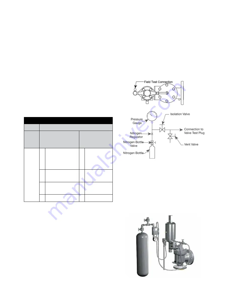
Field Test Connection
A 1/4” FNPT field test connection (Figure 59) is standard
on all pilot valve types. This allows the stroking of the
valve with an auxiliary media, e.g. air or nitrogen. An
internal check valve is present in the field test connection
isolating the inlet media from the test media and at the
same time, allowing the valve to open normally in the
event of a system over pressurization during a field test.
F.2
Pilot Valve Tester
The pilot valve test indicator is available for the
modulating and pop action pilot valves. The valve
test indicator measures the set pressure of the pilot,
while maintaining pressure on the main valve dome
area; thereby, allowing only the pilot to actuate. The
system shown in Figure 60 is available for remote or
local testing.
XX. Setting and Testing (Contd.)
Figure 60: Pilot Valve Tester
Figure 59: Typical Field Test Arrangement
72 | BHGE
© 2018 Baker Hughes, a GE company. All Rights Reserved.


