Installing the switch in an equipment rack
Before you begin
Tool requirements
• a Phillips screwdriver to attach brackets to the switch and the switch to the rack.
Rack requirements
• space of 2.8 inches (7.1 cm) for each switch in an E1A or 1EC standard 19 inch (48.2
cm) equipment rack and T1A 23 inch (58.5 cm) equipment rack.
• appropriate rack space to accommodate 1U switch height (44 mm).
• rack bolted to floor and braced if necessary
• rack must be grounded to the same grounding electrode used by the power service in the
area. The ground path must be permanent and must not exceed 1 Ohm of resistance
from the rack to the grounding electrode.
About this task
Perform the following procedure to install your switch in an equipment rack.
Procedure
1. Ensure power is disconnected from the switch.
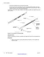
2. Attach a bracket to each side of the switch with the included screws.
The included mounting bracket allows for many different options for front and rear
mounting positions, see the following figures. Attach the brackets in the best position
for your specific equipment rack.
Switch installation
30 VSP 7000 installation
July 2013
Содержание VSP 7000 Series
Страница 4: ...4 VSP 7000 installation July 2013 Comments infodev avaya com ...
Страница 6: ...Installing an MDA 66 Appendix A Hardware reliability 67 6 VSP 7000 installation July 2013 ...
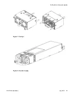
Страница 19: ...Figure 1 Fan trays Figure 2 AC power supply Cooling fans and power supplies VSP 7000 installation July 2013 19 ...
Страница 28: ...Installation preparation 28 VSP 7000 installation July 2013 Comments infodev avaya com ...
Страница 56: ...Fabric Interconnect connectivity 56 VSP 7000 installation July 2013 Comments infodev avaya com ...
Страница 68: ...Hardware reliability 68 VSP 7000 installation July 2013 Comments infodev avaya com ...

