background image

©

 2013 Avaya Inc.

All Rights Reserved.

Notice

While reasonable efforts have been made to ensure that the

information in this document is complete and accurate at the time of

printing, Avaya assumes no liability for any errors. Avaya reserves the

right to make changes and corrections to the information in this

document without the obligation to notify any person or organization of

such changes.

Documentation disclaimer

“Documentation” means information published by Avaya in varying

mediums which may include product information, operating instructions

and performance specifications that Avaya generally makes available

to users of its products. Documentation does not include marketing

materials. Avaya shall not be responsible for any modifications,

additions, or deletions to the original published version of

documentation unless such modifications, additions, or deletions were

performed by Avaya. End User agrees to indemnify and hold harmless

Avaya, Avaya's agents, servants and employees against all claims,

lawsuits, demands and judgments arising out of, or in connection with,

subsequent modifications, additions or deletions to this documentation,

to the extent made by End User.

Link disclaimer

Avaya is not responsible for the contents or reliability of any linked

websites referenced within this site or documentation provided by

Avaya. Avaya is not responsible for the accuracy of any information,

statement or content provided on these sites and does not necessarily

endorse the products, services, or information described or offered

within them. Avaya does not guarantee that these links will work all the

time and has no control over the availability of the linked pages.

Warranty

Avaya provides a limited warranty on its hardware and Software

(“Product(s)”). Refer to your sales agreement to establish the terms of

the limited warranty. In addition, Avaya’s standard warranty language,

as well as information regarding support for this Product while under

warranty is available to Avaya customers and other parties through the

Avaya Support website: 

http://support.avaya.com

. Please note that if

you acquired the Product(s) from an authorized Avaya Channel Partner

outside of the United States and Canada, the warranty is provided to

you by said Avaya Channel Partner and not by Avaya. “Software”

means computer programs in object code, provided by Avaya or an

Avaya Channel Partner, whether as stand-alone products or pre-

installed on hardware products, and any upgrades, updates, bug fixes,

or modified versions.

Licenses

THE SOFTWARE LICENSE TERMS AVAILABLE ON THE AVAYA

WEBSITE, 

HTTP://SUPPORT.AVAYA.COM/LICENSEINFO

 ARE

APPLICABLE TO ANYONE WHO DOWNLOADS, USES AND/OR

INSTALLS AVAYA SOFTWARE, PURCHASED FROM AVAYA INC.,

ANY AVAYA AFFILIATE, OR AN AUTHORIZED AVAYA CHANNEL

PARTNER (AS APPLICABLE) UNDER A COMMERCIAL

AGREEMENT WITH AVAYA OR AN AUTHORIZED AVAYA

CHANNEL PARTNER. UNLESS OTHERWISE AGREED TO BY

AVAYA IN WRITING, AVAYA DOES NOT EXTEND THIS LICENSE IF

THE SOFTWARE WAS OBTAINED FROM ANYONE OTHER THAN

AVAYA, AN AVAYA AFFILIATE OR AN AVAYA AUTHORIZED

AVAYA CHANNEL PARTNER; AVAYA RESERVES THE RIGHT TO

TAKE LEGAL ACTION AGAINST YOU AND ANYONE ELSE USING

OR SELLING THE SOFTWARE WITHOUT A LICENSE. BY

INSTALLING, DOWNLOADING OR USING THE SOFTWARE, OR

AUTHORIZING OTHERS TO DO SO, YOU, ON BEHALF OF

YOURSELF AND THE ENTITY FOR WHOM YOU ARE INSTALLING,

DOWNLOADING OR USING THE SOFTWARE (HEREINAFTER

REFERRED TO INTERCHANGEABLY AS “YOU” AND “END USER”),

AGREE TO THESE TERMS AND CONDITIONS AND CREATE A

BINDING CONTRACT BETWEEN YOU AND AVAYA INC. OR THE

APPLICABLE AVAYA AFFILIATE (“AVAYA”).

Avaya grants you a license within the scope of the license types

described below, with the exception of Heritage Nortel Software, for

which the scope of the license is detailed below. Where the order

documentation does not expressly identify a license type, the

applicable license will be a Designated System License. The applicable

number of licenses and units of capacity for which the license is granted

will be one (1), unless a different number of licenses or units of capacity

is specified in the documentation or other materials available to you.

“Designated Processor” means a single stand-alone computing device.

“Server” means a Designated Processor that hosts a software

application to be accessed by multiple users.

Licence types

Designated System(s) License (DS). End User may install and use

each copy of the Software only on a number of Designated Processors

up to the number indicated in the order. Avaya may require the

Designated Processor(s) to be identified in the order by type, serial

number, feature key, location or other specific designation, or to be

provided by End User to Avaya through electronic means established

by Avaya specifically for this purpose.

Heritage Nortel Software

“Heritage Nortel Software” means the software that was acquired by

Avaya as part of its purchase of the Nortel Enterprise Solutions

Business in December 2009. The Heritage Nortel Software currently

available for license from Avaya is the software contained within the list

of Heritage Nortel Products located at 

http://support.avaya.com/

LicenseInfo

 under the link “Heritage Nortel Products”. For Heritage

Nortel Software, Avaya grants Customer a license to use Heritage

Nortel Software provided hereunder solely to the extent of the

authorized activation or authorized usage level, solely for the purpose

specified in the Documentation, and solely as embedded in, for

execution on, or (in the event the applicable Documentation permits

installation on non-Avaya equipment) for communication with Avaya

equipment. Charges for Heritage Nortel Software may be based on

extent of activation or use authorized as specified in an order or invoice.

Copyright

Except where expressly stated otherwise, no use should be made of

materials on this site, the Documentation, Software, or hardware

provided by Avaya. All content on this site, the documentation and the

Product provided by Avaya including the selection, arrangement and

design of the content is owned either by Avaya or its licensors and is

protected by copyright and other intellectual property laws including the

sui generis rights relating to the protection of databases. You may not

modify, copy, reproduce, republish, upload, post, transmit or distribute

in any way any content, in whole or in part, including any code and

software unless expressly authorized by Avaya. Unauthorized

reproduction, transmission, dissemination, storage, and or use without

the express written consent of Avaya can be a criminal, as well as a

civil offense under the applicable law.

Third Party Components

“Third Party Components” mean certain software programs or portions

thereof included in the Software that may contain software (including

open source software) distributed under third party agreements (“Third

Party Components”), which contain terms regarding the rights to use

certain portions of the Software (“Third Party Terms”). Information

regarding distributed Linux OS source code (for those Products that

have distributed Linux OS source code) and identifying the copyright

holders of the Third Party Components and the Third Party Terms that

apply is available in the Documentation or on Avaya’s website at: 

http://

support.avaya.com/Copyright

. You agree to the Third Party Terms for

any such Third Party Components.

Preventing Toll Fraud

“Toll Fraud” is the unauthorized use of your telecommunications

system by an unauthorized party (for example, a person who is not a

corporate employee, agent, subcontractor, or is not working on your

2     VSP 7000 installation

July 2013

Comments? [email protected]

Содержание VSP 7000 Series

Страница 1: ...Avaya Virtual Services Platform 7000 Series Installation Release 10 2 1 NN47202 300 Issue 04 01 July 2013 ...

Страница 2: ...ortel Software for which the scope of the license is detailed below Where the order documentation does not expressly identify a license type the applicable license will be a Designated System License The applicable number of licenses and units of capacity for which the license is granted will be one 1 unless a different number of licenses or units of capacity is specified in the documentation or o...

Страница 3: ...ird parties Users are not permitted to use such Marks without prior written consent from Avaya or such third party which may own the Mark Nothing contained in this site the Documentation and Product s should be construed as granting by implication estoppel or otherwise any license or right in and to the Marks without the express written permission of Avaya or the applicable third party Avaya is a ...

Страница 4: ...4 VSP 7000 installation July 2013 Comments infodev avaya com ...

Страница 5: ...ns 21 AC power connections 21 Connecting AC power 23 DC power connections 24 Connecting DC power 27 Chapter 5 Switch installation 29 Switch placement options 29 Installing the switch in an equipment rack 30 Installing optional four post rack mount brackets 33 Checking status LEDs to verify switch installation 38 Chapter 6 Fabric Interconnect connectivity 43 Fabric Interconnect 43 Base unit 45 Stac...

Страница 6: ...Installing an MDA 66 Appendix A Hardware reliability 67 6 VSP 7000 installation July 2013 ...

Страница 7: ...000 Documentation Roadmap NN47202 103 Training Ongoing product training is available For more information or to register see http avaya learning com Enter the course code in the Search field and click Go to search for the course Course code Course title 7D00080W Avaya Stackable ERS and VSP Product Overview 7D00085V Stackable ERS VSP Installation Configuration and Maintenance 7D00085I Stackable ERS...

Страница 8: ...name of a topic to see the available list of videos posted on the site Support Visit the Avaya Support website at http support avaya com for the most up to date documentation product notices and knowledge articles You can also search for release notes downloads and resolutions to issues Use the online service request system to create a service request Chat with live agents to get answers to questi...

Страница 9: ...ple 40 Gbps Avaya interface ports for use with other protocols You can use rear port mode to interconnect multiple stand alone VSP 7000 units using FI cables Depending on the rear port mode of operation either seven or eight 40 Gbps interfaces are available over the four FI ports on the rear of the switch FI port Rear port mode Bandwidth Ports UP 1 top right Standard Raw mode 120 Gbps 34 35 36 UP ...

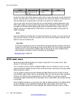
Страница 10: ...erating in Stack mode DToR This is an invalid configuration that causes the rear port mode enabled switch to show ports 33 40 as enabled and up while the stack unit ports 33 40 are not visible and not available Rear port mode on page 50 MDA warm swap Media Dependent Adapter MDA warm swap is supported You can warm insert warm remove or hot remove an MDA You can perform a warm insert by enabling the...

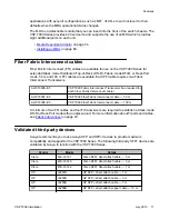
Страница 11: ... Fabric Interconnect cable AL7018007 E5 VSP 7000 Fiber Fabric Interconnect cable 50 m AL7018008 E5 VSP 7000 Fiber Fabric Interconnect cable 100 m A minimum of two FFI cables and four FI transceivers are required to establish a Stack mode DToR or Rear Port mode with an adjacent unit For more information about FI ports and cables see Fabric Interconnect on page 43 Validated third party devices Avaya...

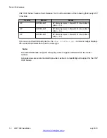
Страница 12: ...63 B21 HP Blade Systems C Class SFP direct attach cable 5 m If you use a verified third party device the show interface gbic command output displays the vendor SEEPROM data and the cable type Note The SEEPROM data output for third party cables might be different than the model number Avaya devices are recommended to provide maximum compatibility and support for the VSP 7000 Series New in this rele...

Страница 13: ...ercurrent protection Ensure that a fuse or circuit breaker no larger than 120 VAC 15 A U S 240 VAC 16 A International is used on the phase conductors Caution This device is a Class A product In a domestic environment this device can cause radio interference in which case the user may be required to take appropriate measures Caution When mounting this device in a rack do not stack units directly on...

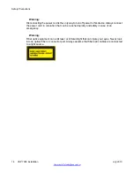
Страница 14: ... reached quickly and safely in case of an emergency Warning Fiber optic equipment can emit laser or infrared light that can injure your eyes Never look into an optical fiber or connector port Always assume that fiber optic cables are connected to a light source Safety Precautions 14 VSP 7000 installation July 2013 Comments infodev avaya com ...

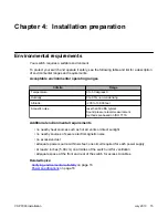
Страница 15: ...s than 50 dBA typical Sound pressure level measurement methods are based on ISO 7779 Additional environmental requirements no nearby heat sources such as hot air vents or direct sunlight no nearby sources of severe electromagnetic noise no excessive dust adequate power source within six feet one circuit required for each power supply at least 2 inches 5 08 cm on all sides of the switch unit for ve...

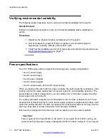
Страница 16: ...perate the switch with two power supplies the switch supports redundancy load sharing and full hot swap replacement of a power supply for uninterruptible operation The power supply is location independent you can install an AC or DC power supply into either power supply slot on the switch For cooling the switch supports two air flow patterns front to back or back to front The air flow direction is...

Страница 17: ...ront airflow modes Cooling fan trays are included and must be installed before operating the switch Power supply compatibility with cooling fans Power supplies support hot swap and are available in two models to support cooling fan airflow modes If you are using front to back cooling or back to front cooling ensure that you use compatible power supplies that match the cooling fan airflow Redundant...

Страница 18: ...nal second power supply for redundancy and load sharing Important Supported cooling air flow directions are front to back or back to front The air flow direction of fan trays and power supplies are labelled and fixed The fan trays and power supplies do not support the ability to change their air flow direction Avaya recommends that you install the first power supply in PSU1 to determine the airflo...

Страница 19: ...Figure 1 Fan trays Figure 2 AC power supply Cooling fans and power supplies VSP 7000 installation July 2013 19 ...

Страница 20: ...ach fan tray is fully seated in the slot and secure each fan tray with two thumb screws 3 Insert each power supply into a rear power supply slot If a blanking plate covers the required power supply slot remove the plate before inserting the power supply 4 Verify that each power supply is fully seated in the slot and securely clipped in place Example The following figures illustrate how to properly...

Страница 21: ... installation perform the AC or DC power connection procedure Related topics AC power connections on page 21 Connecting AC power on page 23 DC power connections on page 24 Connecting DC power on page 27 AC power connections To connect your switch to AC power you require an AC power cord that meets the requirements of your local electrical code International power cord specifications Refer to the f...

Страница 22: ...and then connect the cord to a power outlet You must use the correct power cord for the switch and power supply Country and plug description Specifications Typical plug Continental Europe CEE7 standard VII male plug Harmonized cord HAR marking on the outside of the cord jacket to comply with the CENELEC Harmonized Document HD 21 220 or 230 VAC 50 Hz Single phase U S Canada Japan NEMA5 15P male plu...

Страница 23: ...optional for redundancy and load sharing Connecting AC power Perform the following procedure to connect an AC power source to the switch Before you begin To connect AC power to the switch an appropriate AC power cord is required Ensure the switch power supply supports AC power input About this task Connecting the AC power source to the switch Power connections VSP 7000 installation July 2013 23 ...

Страница 24: ...switch is to disconnect the power Always connect the AC power cord in a location that can be reached quickly and safely in case of an emergency DC power connections To connect your switch to DC power you require DC power cables and ground cables that meet the requirements of your local electrical code Avaya does not supply the cables for connecting the DC power supply to the DC power source Select...

Страница 25: ... off when connecting DC power cables to the back of the switch power supply Verify all terminal connections then connect the DC power cables to your DC power source When you connect the DC power supply to a suitable DC power source the switch powers up immediately You must prepare the cables by stripping insulation from the end of the cable approximately 0 81 inch 2 1 cm before you fasten each cab...

Страница 26: ...Figure 6 DC power supply terminals Installation preparation 26 VSP 7000 installation July 2013 Comments infodev avaya com ...

Страница 27: ...re an appropriate length and gauge for the installation About this task Connecting the DC power source to the switch Procedure 1 Connect a grounding cable from ground to the DC power supply ground terminal 2 Connect the DC leads to the positive and negative DC power supply terminals 3 Tighten the screws on the terminal blocks to secure all cables 4 Attach the opposite ends of the DC leads to a 48V...

Страница 28: ...Installation preparation 28 VSP 7000 installation July 2013 Comments infodev avaya com ...

Страница 29: ...ribes the requirements for the switch environment ambient temperature between 32 F and 122 F 0 C and 50 C relative humidity between 0 and 95 non condensing altitude of 200 to 13 000 feet acoustic noise less than 50dBA typical no nearby heat sources such as hot air vents or direct sunlight no nearby sources of severe electromagnetic noise no excessive dust adequate power source within six feet one ...

Страница 30: ...g electrode used by the power service in the area The ground path must be permanent and must not exceed 1 Ohm of resistance from the rack to the grounding electrode About this task Perform the following procedure to install your switch in an equipment rack Procedure 1 Ensure power is disconnected from the switch 2 Attach a bracket to each side of the switch with the included screws The included mo...

Страница 31: ...Figure 7 Front mounted rack bracket installation options Installing the switch in an equipment rack VSP 7000 installation July 2013 31 ...

Страница 32: ...ations an optional four post rack mounting kit sold separately is available that includes adjustable rear brackets and clamps For more information see Installing optional four post rack mount brackets on page 33 Switch installation 32 VSP 7000 installation July 2013 Comments infodev avaya com ...

Страница 33: ...efore you begin VSP 7000 four post server rack mount kit AL7011001 E6 Tool requirements a Phillips screwdriver to attach brackets to the switch and the switch to the rack a Hex wrench to assemble and attach the optional four post rack mount brackets Rack requirements Space of 2 8 inches 7 1 cm for each switch in an E1A or 1EC standard 19 inch 48 2 cm equipment rack and T1A 23 inch 58 5 cm equipmen...

Страница 34: ...ng electrode Verify that you have all the screws brackets and clamps to assemble and install the four post rack mount kit Figure 10 Four post rack mount kit assembly About this task Perform the following procedure to assemble and install the four post rack mount bracket kit Procedure 1 Attach a front bracket to each guide bracket with four M2 x 3mm long flat head machine screws Switch installation...

Страница 35: ...guide brackets to the switch chassis Figure 12 Attach guide brackets a Use four M4 flat head Phillips machine screws to attach the front of each guide bracket to the switch chassis Installing optional four post rack mount brackets VSP 7000 installation July 2013 35 ...

Страница 36: ...ure 13 Install switch in rack using front rack mounts 4 Attach the rear mounting brackets and secure the switch to the rear rack posts a Slide a rear mounting bracket into each guide bracket channel until flush with the rear rack posts b Secure the rear mounting brackets to the rear rack posts with screws c Secure the rear mounting brackets to the switch chassis with the clamp plates and pan head ...

Страница 37: ...Figure 14 Attach rear mounting brackets Figure 15 Optional rear bracket screws Installing optional four post rack mount brackets VSP 7000 installation July 2013 37 ...

Страница 38: ...ou begin Perform the following tasks before checking the status LEDs Install the fan trays and power supplies Install the switch in an equipment rack or on a shelf Connect power to the switch About this task Perform the following procedure to verify the hardware installation and operation of the unit Procedure 1 Locate the eight status LEDs on the front of the unit see the following figure Switch ...

Страница 39: ...n Base Off The unit is operating in standalone mode If in a Stack the switch is not a Base unit or a Temporary Base unit Amber Solid The unit is operating as the Temporary Base unit Amber Blinking The unit has a Base unit election problem Multiple units are configured with a Base unit switch on or no unit has the Base unit switch on Amber Fast Flashing The unit did not join the Stack Refer to the ...

Страница 40: ...e is not detected or connected to an adjacent unit Amber Solid The FI Up Down cable is detected and connected to an adjacent unit but adjacency with the neighbor is not complete Emerald Solid The FI Up Down cables are detected and connected to an adjacent unit Adjacency with the neighbor is complete Emerald Blinking The unit formed a partial neighbor with an adjacent unit Check the FI Up Down cabl...

Страница 41: ...hin four seconds For an over temperate fault the unit shuts down immediately Note The unit software monitors the internal temperature and generates log and SNMP traps to indicate that the unit is running above the high temperature threshold and is approaching a critical over temperature fault Ruby Blinking The fan tray in position 1 2 is missing You must install a fan tray and the fan tray must ma...

Страница 42: ...rnating The fan tray in position 1 2 does not match the back to front airflow mode of the power supply You must replace the fan tray with a back to front airflow model Sapphire Blink x3 Ruby Solid The fan tray in position 1 2 has degraded and does not match the front to back airflow mode of the power supply You must replace the fan tray with a front to back airflow model Amethyst Blink x3 Ruby Sol...

Страница 43: ...ToR you can efficiently manage the Stack as a single unit In Fabric mode DToR you can deploy multiple stand alone VSP 7000 Series units with Shortest Path Bridging SPB and topology aware configurations Fabric Interconnect ports The Fabric Interconnect ports are a component of the VSP 7000 Series back panel Each switch contains four Fabric Interconnect ports supporting a total FI bandwidth of 640 G...

Страница 44: ... are available in various lengths The following FI cables are supported Order code Description AL7018001 E6 VSP 7000 Fabric Interconnect 0 6 m AL7018002 E6 VSP 7000 Fabric Interconnect 1 5 m AL7018003 E6 VSP 7000 Fabric Interconnect 3 m AL7018004 E6 VSP 7000 Fabric Interconnect 5 m AL7018005 E6 VSP 7000 Active Fabric Interconnect 10 m AL7018006 E5 VSP 7000 Fabric Interconnect Transceiver two requi...

Страница 45: ... the base unit switch to designate a unit in the Stack as the Base unit Slide the base unit switch to the down position to designate a unit as the Base unit You must designate only one switch in a Stack as the Base unit The base unit switch of all the other non base units NBU in the Stack must be in the up position You can verify the Base unit from the base unit switch position and Base LED displa...

Страница 46: ... NBU until the Stack is reset If no FI up or down stack link is present between two NBUs no TBU is assigned during a Base unit failure The TBU is a temporary safeguard only If the Stack loses power the TBU does not power up as the Base unit once power is restored In a long term Base unit failure scenario you are recommended to configure the TBU as the Base unit by configuring the TBU base switch t...

Страница 47: ... simple diagram Note The following sections describe FI down and FI up configurations showing vertical Stack example diagrams The FI cabling for a Stack mode DToR also requires an FI up or FI down cable configuration Stack mode DToR is typically a horizontal deployment of one unit at the top of each equipment rack spanning across up to eight racks FI down configuration In a FI down configuration t...

Страница 48: ... on the designated Base unit unit 1 The FI cables connected to the FI down ports of the Base unit terminates in the FI up ports on the bottom unit in the Stack This bottom unit is designated unit 2 The Stack is wired upwards though the units and the software continues to number up though the Stack In this configuration the Base unit discovers the Stack in a FI up direction The following illustrati...

Страница 49: ...ed or damaged other units in the stack can remain operational without interruption In a redundant configuration the software uses the FI cables to provide two paths between units If one path fails the data can travel over the remaining path with half of the normal FI bandwidth The following is an example of how a redundant FI configuration reacts to a failed connection Failure example Unit 3 becom...

Страница 50: ...ort mode Bandwidth Port interface UP 1 right top connector Standard Raw mode 120 Gbps 34 35 36 UP 2 right bottom connector Standard Raw mode 40 Gbps 33 DOWN 1 left top connector Standard Raw mode 120 Gbps 38 39 40 DOWN 2 left bottom connector Standard Raw mode 40 Gbps 37 UP 1 right top connector SPB Fabric mode DToR 120 Gbps 34 35 36 UP 2 right bottom connector SPB Fabric mode DToR 40 Gbps 33 DOWN...

Страница 51: ...anging rear port mode and answering yes to the confirmation prompt results in a switch configuration reset equivalent to a partial default command When you enable rear port mode the switch applies the following default settings to all FI ports on the rear of the chassis VLAN tagging for rear ports is set to tagAll The LACP administration key is set to 4095 The LACP operating mode for rear ports is...

Страница 52: ...Platform 7000 Series Installation NN47202 300 For more information about configuring rear port mode see Avaya Virtual Services Platform 7000 Series Getting Started NN47202 303 Fabric mode DToR configurations Each switch has a pair of FI up and FI down ports You can enable the rear port mode on standalone VSP 7000 Series units to configure in a Fabric mode Distributed Top of Rack DToR or a rear por...

Страница 53: ...e 43 Note For Stack configurations consider each pair of FI ports on a unit as a single connection Each pair of FI ports requires two FI cables Ensure to order a minimum of two matched FI cables for each unit For a redundant configuration you require one matched pair of longer FI cables to complete the loop from the bottom unit to the top unit About this task Use the following procedure to install...

Страница 54: ...s switch The FI cable label can obscure your view of the connection You must ensure that the FI cable connector alignment slot and cable connector pull tab is facing up Figure 25 Installing Fabric Interconnect cables Fabric Interconnect connectivity 54 VSP 7000 installation July 2013 Comments infodev avaya com ...

Страница 55: ...R configurations select a Base unit for the Stack Use the Base unit switch to configure one unit as the Base unit Important Only one unit can operate as the Base unit Ensure that only one switch is configured as the Base unit The switch on all other units must be in the non base unit position 4 Connect AC power If you assigned the Base unit and non base units with the units powered on you must res...

Страница 56: ...Fabric Interconnect connectivity 56 VSP 7000 installation July 2013 Comments infodev avaya com ...

Страница 57: ... port Out of Band Management port and a USB 2 0 port Figure 27 Console and management ports See the following sections for more information Console port The console port is the RJ45 port with a blue border outline The port is labelled console and can be used to establish a management terminal connection to the switch You can use an VSP 7000 installation July 2013 57 ...

Страница 58: ... CTS clear to send Optional can be swapped or linked with pin 1 Out of Band Management port The Out of Band Management port is the RJ45 port directly below the console port The port is labelled management and can support 10 100 1000 Ethernet connections The Out of Band Management port is available for use when the switch is running diagnostic or agent software You can use the Out of Band Managemen...

Страница 59: ...ble transceivers can support various media types modes and cable distances of up to 70 km Any cable reach over 100 m requires fiber optic cable You must select appropriate transceivers and cabling that can support your required cable distances and network architecture The following tables show the supported SFP and SFP transceivers Table 3 Supported SFP transceivers SFP device Order code 1 PORT 10...

Страница 60: ... PORT 1000BASE T SFP RJ 45 AA1419043 E6 1000BASE SX SFP DDI LC AA1419048 E6 1000BASE LX SFP DDI LC AA1419049 E6 1 PORT 1000BASE XD SFP DDI LC 1310NM AA1419050 E6 1 PORT 1000BASE XD SFP DDI LC 1550NM AA1419051 E6 1 PORT 1000BASE ZX SFP DDI LC 1550NM AA1419052 E6 1 PORT SFP 1000BASE CWDM DDI LC 1470NM up to 40 km AA1419053 E6 1 PORT SFP 1000BASE CWDM DDI LC 1490NM up to 40 km AA1419054 E6 1 PORT SFP...

Страница 61: ...air with AA1419076 E6 AA1419077 E6 Note LC Lucent Connector Validated third party devices Avaya recommends you to use Avaya SFP and SFP devices to provide maximum compatibility and support for the VSP 7000 The following third party SFP devices are validated by Avaya to function with the VSP 7000 Series Vendor Model Details Cisco 450 16141 Cisco SFP direct attach cable 5 m Cisco 450 16140 Cisco SFP...

Страница 62: ...s The switch front panel contains transmit Tx and receive Rx LEDs for each port The following table describes the SFP port LED status LED State Description Tx Off No SFP or SFP transceiver detected Emerald Solid SFP detected and link established Emerald Flashing SFP link established and transmitting Amber Solid SFP detected and link established Amber Flashing SFP link established and transmitting ...

Страница 63: ...e cabling installation for efficient routing and future maintenance accessibility Verify that the SFP or SFP transceivers and network cabling support your network configuration For more information about SFP and SFP transceivers see Avaya Virtual Services Platform 7000 Installation SFP and SFP NN47202 302 About this task Important The VSP 7024XLS supports SFP and SFP as the primary network interfa...

Страница 64: ...he network interface cover from the pluggable transceiver if applicable and insert an appropriate network interface cable into the transceiver 6 Connect the opposite end of the network interface cable into the required network device 7 Repeat all steps until you have completed your transceiver and network cabling installation Media Dependent Adapter The Media Dependent Adapter MDA is a field repla...

Страница 65: ...raffic within the switch or stack You can perform a warm removal by disabling the MDA before removal A warm removal ensures MDA egress traffic routes to an operating switch port Hot removal is also supported however a hot removal can cause packet loss Once an MDA is hot removed packets scheduled to egress the MDA ports are discarded and an unsafe MDA removal log message is generated When the MDA i...

Страница 66: ... MDA so that the card edges line up with the card guides in the chassis 6 Insert and slide the MDA into the opening on the front of the chassis Firmly press the MDA into the MDA slot until it is fully seated Important Inserting the MDA can require a large amount of force to ensure that the MDA is fully seated 7 Verify that the MDA is fully seated and tighten the two thumb screws to secure the MDA ...

Страница 67: ...rdware Important You must install the switch and it s components correctly and operate the hardware within the supported environmental conditions The MTBF values in the following table do not include failure caused by software or human error Hardware MTBF Calculated VSP 7024XLS base unit no fans no power supplies 261 500 hours Fan tray Back to Front or Front to Back 1 000 000 hours Power supply 30...

Страница 68: ...Hardware reliability 68 VSP 7000 installation July 2013 Comments infodev avaya com ...

Отзывы: