


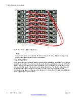


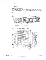


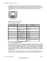


Figure 19: Base unit switch and management ports
Temporary base unit
If a Base unit failure occurs, the next downstream unit (FI down configuration), or furthest
upstream unit (FI up configuration), becomes a Temporary Base unit (TBU). An amber Base
LED indicates a unit operating as the TBU.
Note:
The automatic failover process can continue to assign a TBU until there are only two units
left in the Stack.
• If a former Base unit rejoins the Stack, it operates as a NBU until the Stack is reset.
• If no FI up or down stack link is present between two NBUs, no TBU is assigned during
a Base unit failure.
The TBU is a temporary safeguard only. If the Stack loses power, the TBU does not power up
as the Base unit once power is restored. In a long term Base unit failure scenario, you are
recommended to configure the TBU as the Base unit by configuring the TBU base switch to
Base. Once the failed unit is repaired or replaced, check all unit base switches to ensure only
one unit in the stack is configured as the Base unit.
Important:
Fabric Interconnect connectivity
46 VSP 7000 installation
July 2013
Содержание VSP 7000 Series
Страница 4: ...4 VSP 7000 installation July 2013 Comments infodev avaya com ...
Страница 6: ...Installing an MDA 66 Appendix A Hardware reliability 67 6 VSP 7000 installation July 2013 ...
Страница 19: ...Figure 1 Fan trays Figure 2 AC power supply Cooling fans and power supplies VSP 7000 installation July 2013 19 ...
Страница 28: ...Installation preparation 28 VSP 7000 installation July 2013 Comments infodev avaya com ...
Страница 56: ...Fabric Interconnect connectivity 56 VSP 7000 installation July 2013 Comments infodev avaya com ...
Страница 68: ...Hardware reliability 68 VSP 7000 installation July 2013 Comments infodev avaya com ...