


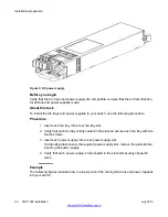


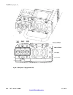


Figure 4: Installing the fan trays and power supplies
Next steps
Once you have installed the two fan trays and at least one power supply, you can install and
connect power to the switch.
Power connections
The following sections describe the steps to connect power sources to the switch. Depending
on your type of installation, perform the AC or DC power connection procedure.
Related topics:
on page 23
on page 27
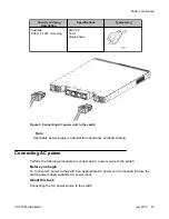
AC power connections
To connect your switch to AC power you require an AC power cord that meets the requirements
of your local electrical code.
International power cord specifications
Refer to the following table for power cord plug specifications.
Voltage:
Power connections
VSP 7000 installation
July 2013 21
Содержание VSP 7000 Series
Страница 4: ...4 VSP 7000 installation July 2013 Comments infodev avaya com ...
Страница 6: ...Installing an MDA 66 Appendix A Hardware reliability 67 6 VSP 7000 installation July 2013 ...
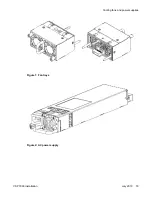
Страница 19: ...Figure 1 Fan trays Figure 2 AC power supply Cooling fans and power supplies VSP 7000 installation July 2013 19 ...
Страница 28: ...Installation preparation 28 VSP 7000 installation July 2013 Comments infodev avaya com ...
Страница 56: ...Fabric Interconnect connectivity 56 VSP 7000 installation July 2013 Comments infodev avaya com ...
Страница 68: ...Hardware reliability 68 VSP 7000 installation July 2013 Comments infodev avaya com ...