213
4317I–AVR–01/08
AT90PWM2/3/2B/3B
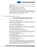
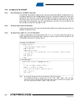
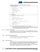
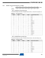
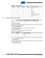
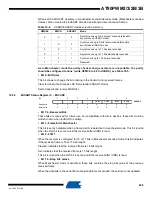
Th e f r a m e f o rm a t u s e d b y t h e E U S A R T c a n b e c o n f i g u r e d th r o u g h t h e f o l l o w i n g
USART/EUSART registers:
•
UTxS3:0 and URxS3:0 (EUCSRA of EUSART register) select the number of data bits per
frame
•
UPM1:0 bits enable and set the type of parity bit (when configured in Manchester mode, the
parity should be fixed to none).
USBS (UCSRC register of USART) and EUSBS (EUCSRB register of EUSART) select the num-
ber of stop bits to be processed respectively by the transmiter and the receiver. The receiver
stores the two stop bit values when configured in Manchester mode. When configured in level
encoded mode, the second stop bit is ignored (behavior similar as the USART).
19.3.2
Parity Bit Calculation
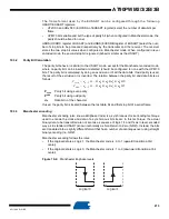
The parity bit behavior is similar to the USART mode, except for the Manchester encoded mode,
where no parity bit can be inserted or detected (should be configured to none with the UPM1:0
bits. The parity bit is calculated by doing an exclusive-or of all the data bits. If odd parity is used,
the result of the exclusive or is inverted. The relation between the parity bit and data bits is as
follows:
P
even
Parity bit using even parity
P
odd
Parity bit using odd parity
d
n
Data bit n of the character
If used, the parity bit is located between the last data bit and first stop bit of a serial frame.
19.3.3
Manchester encoding
Manchester encoding (also know as Biphase Code) is a synchronous clock encoding technique
used to encode the clock and data of a synchronous bit stream. In this technique, the actual
binary data to be transmitted are not sent as a sequence of logic 1's and 0's as in level encoded
way as in standard USART (known technically as Non Return to Zero (NRZ)). Instead, the bits
are translated into a slightly different format that has a number of advantages over using straight
binary encoding (i.e. NRZ).
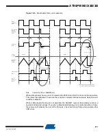
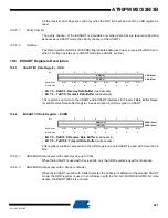
Manchester encoding follows the rules:
•
If the original data is a Logic 1, the Manchester code is: 0 to 1 (upward transition at bit
center)
•
If the original data is a Logic 0, the Manchester code is: 1 to 0 (downward transition at bit
center)
Figure 19-2. Manchester Bi-phase levels
P
even
d
n
1
–
…
d
3
d
2
d
1
d
0
0
P
o dd
⊕
⊕
⊕
⊕
⊕
⊕
d
n
1
–
…
d
3
d
2
d
1
d
0
1
⊕
⊕
⊕
⊕
⊕
⊕
=
=
Logical 0
Logical 1
Содержание AT90PWM2
Страница 344: ...346 4317I AVR 01 08 AT90PWM2 3 2B 3B 31 1 SO24...
Страница 345: ...347 4317I AVR 01 08 AT90PWM2 3 2B 3B 31 2 SO32...
Страница 346: ...348 4317I AVR 01 08 AT90PWM2 3 2B 3B 31 3 QFN32...
Страница 347: ...349 4317I AVR 01 08 AT90PWM2 3 2B 3B...


