220
4317I–AVR–01/08
AT90PWM2/3/2B/3B
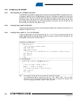
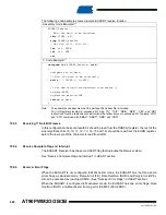
The following code example shows a simple EUSART receive function.
Note:
The example code assumes that the part specific header file is included.
For I/O Registers located in extended I/O map, “IN”, “OUT”, “SBIS”, “SBIC”, “CBI”, and “SBI”
instructions must be replaced with instructions that allow access to extended I/O. Typically “LDS”
and “STS” combined with “SBRS”, “SBRC”, “SBR”, and “CBR”.
19.5.3
Receiving 17 Data Bit Frames
In this configuration the seventeenth bit shoud be read from the RXB8 bit register, the rest of the
most significant bits (9, 10, 11, 12, 13, 14, 15 and 16) should be read from the EUDR register,
before the low byte of the character is read from UDR.
19.5.4
Receive Complete Flag and Interrupt
The EUSART Receiver has the same USART flag that indicates the Receiver state.
See “Receive Complete Flag and Interrupt” in USART section.
19.5.5
Receiver Error Flags
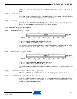
When the EUSART is not configured in Manchester mode, the EUSART has the three same
errors flags as standard mode: Frame Error (FE), Data OverRun (DOR) and Parity Error (UPE).
All can be accessed by reading UCSRA. (See “Receiver Error Flags” in USART section).
When the EUSART is configured in Machester mode, the EUSART has two errors flags: Data
OverRun (DOR), and Manchester framing error (FEM bit of EUCSRC).
Assembly Code Example
(1)
EUSART_Receive:
;
Wait for data to be received
sbis
UCSRA, RXC
rjmp
EUSART_Receive
;
Get MSB (r15), LSB (r16)
lds
r15, EUDR
lds
r16, UDR
ret
C Code Example
(1)
unsigned int
EUSART_Receive(
void
)
{
unsigneg int rx_data
/*
Wait for data to be received
*/
while
( !(UCSRA & (1<<RXC)) )
;
/*
Get and return received data from buffer
*/
rx_data=EUDR;
rx_data=rx_data<<8+UDR;
return
rx_data;
}
Содержание AT90PWM2
Страница 344: ...346 4317I AVR 01 08 AT90PWM2 3 2B 3B 31 1 SO24...
Страница 345: ...347 4317I AVR 01 08 AT90PWM2 3 2B 3B 31 2 SO32...
Страница 346: ...348 4317I AVR 01 08 AT90PWM2 3 2B 3B 31 3 QFN32...
Страница 347: ...349 4317I AVR 01 08 AT90PWM2 3 2B 3B...

