160
4317I–AVR–01/08
AT90PWM2/3/2B/3B
Note : Do not set the PARUNn bits on the three PSC at the same time.
Thanks to this feature, we can for example configure two PSC in slave mode (PARUNn = 1 /
PRUNn = 0) and one PSC in master mode (PARUNm = 0 / PRUNm = 0). This PSC master can
start all PSC at the same moment ( PRUNm = 1).
16.22.1
Fault events in Autorun mode
To complete this master/slave mechanism, fault event (input mode 7) is propagated from PSCn-
1 to PSCn and from PSCn to PSCn-1.
A PSC which propagate a Run signal to the following PSC stops this PSC when the Run signal
is deactivate.
According to the architecture of the PSC synchronization which build a “daisy-chain on the PSC
run signal” beetwen the three PSC, only the fault event (mode 7) which is able to “stop” the PSC
through the PRUN bits is transmited along this daisy-chain.
A PSC which receive its Run signal from the previous PSC transmits its fault signal (if enabled)
to this previous PSC. So a slave PSC propagates its fault events when they are configured and
enabled.
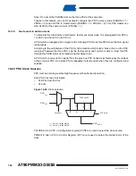
16.23 PSC Clock Sources
PSC must be able to generate high frequency with enhanced resolution.
Each PSC has two clock inputs:
•
CLK PLL from the PLL
•
CLK I/O
Figure 16-39. Clock selection
PCLKSELn bit in PSC n Configuration register (PCNFn) is used to select the clock source.
PPREn1/0 bits in PSC n Control Register (PCTLn) are used to select the divide factor of the
clock.
CLK
CLK
PSCn
CLK
PLL
I/O
CK
CK/4
CK/32
CK/256
PRESCALER
CK
PPREn1/0
00
01
10
11
PCLKSELn
1
0
(1)
(2)
(1) : CK/16 for AT90PWM2/3
(2) : CK/64 for AT90PWM2/3
Содержание AT90PWM2
Страница 344: ...346 4317I AVR 01 08 AT90PWM2 3 2B 3B 31 1 SO24...
Страница 345: ...347 4317I AVR 01 08 AT90PWM2 3 2B 3B 31 2 SO32...
Страница 346: ...348 4317I AVR 01 08 AT90PWM2 3 2B 3B 31 3 QFN32...
Страница 347: ...349 4317I AVR 01 08 AT90PWM2 3 2B 3B...


