82
© 2019, ATEÏS, member of PAX ProAV Group
3. Set the number of secondary local unit (BTQ-SL8) connected to the main controller/BTQ-SG8
unit.
4. Last, the total number of the connected secondary units will be automatically sum up and
display in the row of [SEC].
5. After completed all the settings, click [Next] to move to [Step 3: number of remotes] settings.
5.1.1.1.3 Step 3: number of remotes
Set the number of DPM8/DPM-T5/CD-8DF/CD-16DF/CD-T5DF for your BOUTIQUE system, the
default number of DPM8 is 1, and DPM-T5/CD-8DF/CD-16DF/CD-T5DF is 0.
1. Set the number of DPM8/DPM-T5/CD-8DF/CD-16DF/CD-
T5DF which are connected to the corresponded main
controller and secondary units.
2. Click [Next] to move to [Step 4: power amplifiers sharing]
settings.
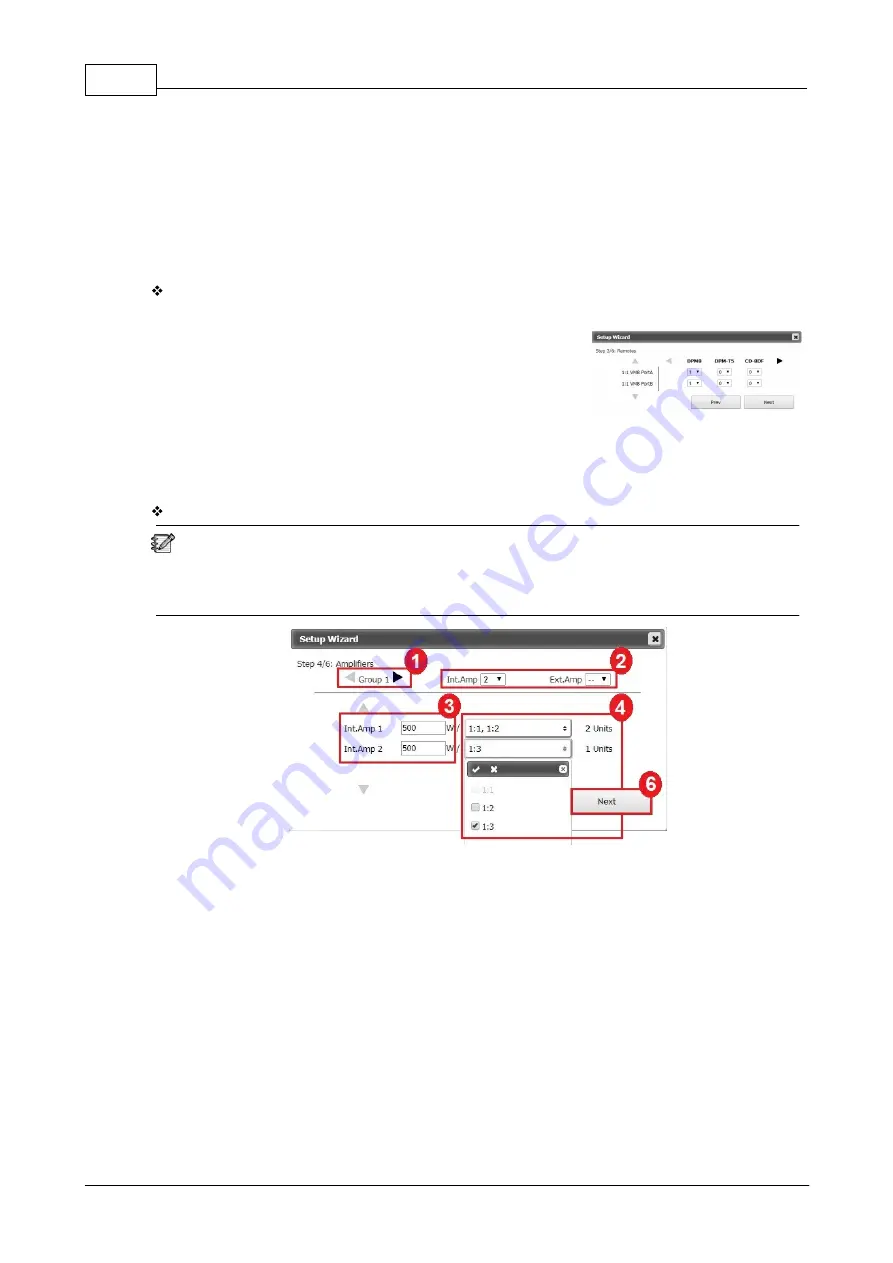
5.1.1.1.4 Step 4: power amplifier(s) sharing
Set the group of internal/external power amplifier connected to the BOUTIQUE system.
All the paging calls and BGM can be amplified by internal power amplifier from the main
controller and the external power amplifier. The internal amplifier can also share its power with
other secondary unit. An external amplifier can also be connected for spare switching. Therefore,
you can define which amplifier in the same group in order to share its power.
1. Set the group based on the number of local-net the BOUTIQUE system has. The Group 1
indicates the amplifiers in the first local network, the Group 2 indicates the second local
network, and so on.
2. Set the number of amplifier for Int. amp channel and Ext. amp channel in the selected group.
3. Set the power (wattage) of which Int./Ext. amplifier channel.
4. Then select which device shall be used for power sharing by choosing the ID from the drop-
down box. For example, see the picture above, the main controller (1:1) will share the power
with the secondary unit (1:2) through Int. Amp 1 channel. And an external amplifier will be
connected to another secondary unit (1:3) through Int. Amp 2 channel.
5. Proceed the same steps to set the power sharing for the rest of external amplifiers.
6. Click [Next] to move to [Step 5: dummy load capacitor] settings.


