Hardware configuration & operation
55
© 2019, ATEÏS, member of PAX ProAV Group
4
Hardware configuration & operation
After completed the hardware connection in the previous chapters, please proceed the hardware
configuration. If this is the first system setup, users can easily do the hardware configuration directly
from LCD touch panel of BTQ-VM4/8 controller, see
More advanced configuration such as DSP parameters adjustment, event and bell scheduler etc..
can be configured by a dedicated ATEÏS web browser, see
4.1
BTQ-VM LCD panel
4.1.1
Setup wizard
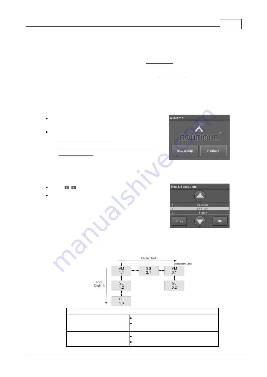
The LCD touch panel on main controller provides system configuration, control and system status
display.
After completed the hardware wiring, the LCD panel
will activate automatically once it is powered.
Press the touch panel to start the system setup.
1.
2.
Replace (replace the broken main controller
with the new one)
4.1.1.1
New setup
4.1.1.1.1 Step 1: language
Press [
] on touch panel to set the language.
Press [OK].
4.1.1.1.2 Step 2: number of main and secondary units & ID
Set the number of main controller and secondary unit and its ID in the system. The ID is composed
of the number of X, Y. X indicates the global net ID and Y is the local net ID.
Network
Local Network:
*for BTQ-SL8 connection
Max. digi-link units: 31
Max. cable length: 10m between units
(shielded RJ45 connector, STP CAT5/6)
Global Network:
*for BTQ-VMxx/BTQ-SG8
Max. global net units: 64
Max. cable length: 100m between units


