background image


PROGRAMMING THE TABBER 


66 

2.


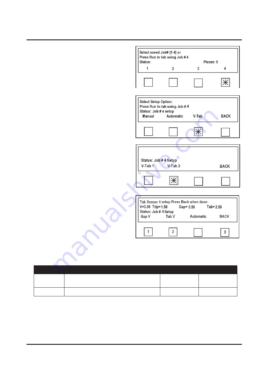
Then select Job # 

4

 from  

Select saved Job#

 screen. 


3.


Before you can set up Job, you must set 
up Tabber Sensors to read tab. Select 

V-Tab

 and follow instructions. 


4.


Next screen allows you to select Head 
that you are using to tab. In this case, 
we are using Head 2, so select 

V Tab 2


5.


To manually programming V Tab 
voltage:

 Begin by finding Gap V (

or 

voltage return from space between 
Stamps in this case.

) Release Hold 

Down Roller Latch so stamps can slide 
easily through Sensor. Move stamp 
web through Sensor until you obtain 
lowest voltage reading , then press 

Gap 

V

 key (1). Continue moving stamp web through Sensor until you obtain highest reading, 

then press 

Tab V

 key (2). When finished, press 

BACK

 key (3). 


NOTE: When setting Gap Voltage and Tab Voltage manually, software determines if  
Tab Type is Opaque or Clear based on voltage readings. 


Tab Type 

Description 

Gap V Level 

Tab V Level 

Opaque 

Tabs in which space between tabs is lighter 
than Tab even if tab is white. 

Low 

High 

Clear 

Tabs that have a black line between tabs. 

High 

Low 

Содержание ATS-309

Страница 1: ...ASTRO ATS 309 MULTI TABBER STAMP AFFIXER OPERATOR MANUAL ...

Страница 2: ...quipment 9 Make sure there is no strain on the power cord caused by jamming it between equipment walls or furniture 9 DO NOT remove covers Covers enclose hazardous parts that should be accessed by a qualified service representative Report any cover damage to your service representative 9 This machine requires periodic maintenance Contact your authorized service representative for required service ...

Страница 3: ...ading Tabs Head 1 or Head 2 17 Head 1 Adjustment General 18 Head 1 Adjustment Side Tabbing 19 Head 1 Adjustment End Tabbing 21 Head 1 Adjustment Applying Stamps 24 Head 2 Adjusting for Side Tabbing 26 Operating Tabber 28 Understanding Start up Screen 29 Exceeding Tabbing Rate 30 Select and Run a Pre Programmed Job 30 Fine Tuning Adjustments 32 Side Tab Positioning 32 Head 1 Side Tab Adjustment 33 ...

Страница 4: ... SECTION 5 Maintenance 72 Cleaning 72 Rollers and Transport Belts 72 Shafts with Movable Parts 72 Cleaning Sensors 73 Sensor locations 73 Media Sensor Test 73 Tab Sensor Test 74 Cleaning Tab Wrap Guides 74 Lubrication 75 SECTION 6 Troubleshooting 76 Jams 76 Tab Placement Problems 77 Stamp Placement Problems 79 Tabber Operation Problems 80 Diagnostics 80 Appendix A Specifications 83 Appendix B Iden...

Страница 5: ... tab web after tab is applied 7 Left Media Guide Assembly Transports media to tabbing area Guide is not adjustable 8 Main Power Switch Receptacle Tabber Power cord plugs in here Switch turns Tabber ON and OFF 9 Center Support Plate Used to support media 6 5 wide or larger This plate also contains slot used when tabbing at lead edge of a piece 10 Right Media Guide Assembly Transports media to tabbi...

Страница 6: ...e is used when tabbing on end of a piece 6 Exit Foot Holds media down as it travels under Exit Rollers Adjusted with Head 1 7 Tab Wrap Guide Head 1 Wraps tab around media when Side Tabbing 8 Exit Pressure Rollers Provide pressure to transport media and seal tabs 9 Tab Wrap Guide Head 2 Wraps tab around media when Tabbing 10 Exit Roller Assembly Securing Latches Locks down Exit Roller Assembly 11 E...

Страница 7: ...ed when this feature is not used 2 Emergency Stop Output Permits Tabber to control emergency stopping of another machine 3 Tabber Feeder Connection Feeder connects here to permit automatic operation of Feeder when used with Tabber 4 Main Power Switch Tabber Turns Tabber ON and OFF 5 Fuse Main power fuse 2 5A 250V for Tabber CAUTION Disconnect power before replacing fuse 6 Power Inlet Tabber Power ...

Страница 8: ...d here 4 Main Power Switch Feeder Turns Feeder ON and OFF 5 Mode Switch Permits selection of either Automatic Mode Tabber controls Feeder or Manual Mode Feeder speed is controlled manually by Feeder Speed Control 6 Feeder Speed Control Controls Feeder speed when Feeder mode switch is in Manual position 7 Media Thickness Adjustment Feeder Adjusts Exit Rollers of Feeder for thicker media Loosen knob...

Страница 9: ...op Tab placed on end of piece is not counted in the above 3 LED Display Informs operator of Tabber status 4 Key Pad Used to enter data to program Tabber 5 Emergency Stop When Tabber is properly connected to Feeder and or other pieces of equipment activating this button stops machines 6 Soft Keys Used to step through various menu options to program Tabber 7 Stop Key Pressing this key stops Tabber a...

Страница 10: ...rk surface Protect Tabber from excessive heat dust and moisture avoid placing it in direct sunlight CAUTION UNIT IS HEAVY STRONGLY RECOMMENDED THAT TWO TECHNICIANS REMOVE TABBER FROM CARTON AND PLACE IT ON WORKING SURFACE Install Reel Supports Two Reel Supports have to be installed Remove upper mounting screw and loosen lower mounting screw Slide Reel Supports over Frame until they bottom on lower...

Страница 11: ...r Make sure that Tabber Emergency Stop Switch is turned OFF and Main Power Switch above Power Cord Receptacle is turned OFF Make sure that Power Switch on Feeder is turned OFF 1 Connect one end of Tabber power cord 1 to rear of Tabber in corresponding receptacle 2 Connect one end of Feeder power cord 2 to rear of Feeder in corresponding receptacle 3 Plug other cord ends into a 115 Volt AC 220 VAC ...

Страница 12: ...ION CORDS TO CONNECT TABBER OR FEEDER TO WALL RECEPTACLE DO NOT USE OUTLETS CONTROLLED BY WALL SWITCHES DO NOT USE AN OUTLET THAT SHARES SAME CIRCUIT WITH LARGE ELECTRICAL MACHINES OR APPLIANCES 4 Connect Feeder Interface Cable 3 to Feeder and to lower connector on Tabber ...

Страница 13: ..._______________________ _____________________________________________________________________________________________ _____________________________________________________________________________________________ _____________________________________________________________________________________________ _____________________________________________________________________________________________ ...

Страница 14: ...djust Head positions side tab or end tab for application x Program Job x Run Job Mechanical Set up Once you determine tab location and number of tabs you are ready to set up Tabber for handling media and placing tabs IMPORTANT TO PERMIT PROPER FEEDING THROUGH TABBER MEDIA USED TO TAB STAMP MUST HAVE SQUARE TIGHT FOLDS AND BE NEARLY UNIFORMLY THICK IF MEDIA DOES NOT FEED PROPERLY IT WILL NOT BE TAB...

Страница 15: ...RT PLATE AND HOLD DOWN GUIDE MUST BE INSTALLED WHEN USING MEDIA THAT MEASURES 6 5 OR WIDER FOR MEDIA LESS THAN 6 5 GO TO NARROW MEDIA SET UP ON PAGE 13 3 Loosen securing knob for Right Media Guide NOTE Right Media Guide is movable Left Media Guide is fixed 4 Turn ON Tabber s Main Power Switch Verify that Exit Roller Assembly is closed and secured lock latches Verify that Emergency Stop Button is r...

Страница 16: ... used to accomplish this step IMPORTANT IF MEDIA IS NOT FOLDED SQUARE MAKE INITIAL SETTING OF GUIDE AT WIDEST POINT ON PIECE ONCE INITIAL ADJUSTMENT IS MADE MEDIA WIDTH FINE ADJUSTMENT CAN BE USED TO FINE TUNE RIGHT HAND GUIDE 8 Secure Right Media Guide s position using Locking Knob 9 Press STOP button to stop Tabber 10 Slide Exit Foot Knob towards operator side until it stops against Right Media ...

Страница 17: ...a Guide has a Side Rail 1 held in place by two screws Used for front tabbing media between 5 and 6 1 2 and can be removed when running very narrow media and stamps Running Tri Fold Long Edge 1 Remove Side Rail 1 see photo above 2 Remove Standard Support Plate 3 Install Narrow Media Guide in place of Standard Support Plate 4 Adjust Narrow Media Guide to width of Tri Fold media then move Transport B...

Страница 18: ...p Head 1 to apply stamps 5 Run Job Applying Three Tabs to a Narrow Piece 1 Install Standard Media Guide in place 2 Install Side Rail on Narrow Media Guide if not already installed 3 Place Narrow Media Guide with Side Rail against Standard Media Guide just on edge of media 4 Move Transport Belt Guide against Narrow Media Guide 5 Set up Tabber to tab three tabs two on Head 2 and one on front from He...

Страница 19: ...oller Assembly 3 Insert one piece of Media into exit end of Tabber and adjust Media Thickness Control Knob counterclockwise lowering Exit Roller Assembly until you start to feel a drag on media 4 Continue to turn Media Thickness Control Knob counterclockwise an additional 3 or 4 clicks to obtain proper transport pressure on media 5 If installed loosen thumbscrew for Hold Down Guide and allow Guide...

Страница 20: ... to the media before tightening Locking Knobs This gives thicker media a little more room to feed 3 Move non operator Side Guide to within 1 32 of media and tighten Locking Knob 4 Adjust Rear Media Support Guide so media is approximately 1 2 above Media Support as shown NOTE The above is a starting guideline Height of media above Support Guide may vary to obtain optimum feeding 5 Forwarding Roller...

Страница 21: ...eel Side Guide and install Tab Roll with tabs unwinding face up from right side of roll Remove approximately 20 tabs from roll to create a leader 2 Thread leader over Reel Brake Roller 3 Thread leader over Idler Roller and then through Tab Sensor Reposition Tab Guide located on Idler Roller to accommodate tab width 4 Continue threading leader around Tab Applicator Peel Point NOTE Head 1 has two pe...

Страница 22: ... Head 1 first determine if you will be tabbing on the side of a piece or tabbing or stamping on the end of a piece 1 Tab Separator on Head 1 has a two position peeling plate one for side tabbing and the other for center tabbing Adjusted by loosening locking screw and moving it up for end tabbing and down for side tabbing Position of Tab Separator is critical Always check this when changing Head 1 ...

Страница 23: ...er should be set up to feed media before this procedure is used 1 Unlatch Exit Roller Assembly swing it open and then adjust Peel Plate for side tabbing 2 Lift Tab Drive Pressure Roller Release Latch on Head 1 to release pressure between tab stock and Tab Drive Roller ...

Страница 24: ...d then tighten Securing Knob NOTE This image shows how center point of tab should align with exit end of Right Media Guide Assembly Please note that tab in this image is protruding further than necessary When initially adjusting tab starting point tab should just start to protrude from Applicator Also note that a tab that is 1 1 2 in diameter will not perfectly center on the assembly It is importa...

Страница 25: ... Fine Adjustment Knob to make small corrections to fold position of tabs being applied by Head 1 Refer to Fine Tuning Adjustments for more information 13 When satisfied with tab position open Exit Roller Assembly and adjust Head 1 Stop against Head 1 Close and lock Exit Roller Assembly 14 This completes setup for Head 1 to side tab IMPORTANT IF ONLY USING HEAD 1 MAKE SURE THAT HEAD 2 IS DISABLED I...

Страница 26: ...ture in Step 4 above and loosen Head 1 Securing Knob slide Head 1 over Right Media Guide Assembly as shown Center tab in slot in Media Support as shown and then tighten Securing Knob NOTE This image shows how center point of tab should align with center of Media Support Plate Note that tab in image is protruding about the correct amount for end tabbing Also note that a tab that is 1 1 2 in diamete...

Страница 27: ...Feeder 12 Check positioning of tab or tabs on second piece If an adjustment in tab position is required use Head Fine Adjustment Knob to make small corrections to side to side tab position of tabs being applied by Head 1 refer Fine Tuning Adjustments section for more information 13 When you are satisfied with tab position open Exit Roller Assembly and adjust Head 1 Stop against Head 1 Close and lo...

Страница 28: ...EN INITIALLY SETTING UP TABBER FOR APPLYING STAMPS ONCE YOU ARE COMFORTABLE WITH SETUP YOU CAN SWITCH TO USING LIVE STAMPS TEST STAMPS ARE AVAILABLE FROM POST OFFICE 1 Adjust Tab Applicator s peel point to side tabbing position as you would when applying tabs 2 Unlatch Exit Roller Assembly swing it open and then adjust Peel Plate for side tabbing 3 Lift tab drive Pressure Roller Release Latch on H...

Страница 29: ...wn and then tighten Securing Knob NOTE This image shows how center point of stamp should align with exit end of Right Media Guide Assembly When initially adjusting stamp starting point stamp should just start to protrude from Applicator It is important that stamp backing is against side of Tab Sensor Guide in all cases Sensor position is where notch in Guide is positioned 8 Close Exit Roller Assem...

Страница 30: ...ake small corrections to location of stamp being applied by Head 1 You can refer to section on Fine Tuning Adjustments for more information 14 When you are satisfied with stamp position open Exit Roller Assembly and adjust Head 1 Stop against Head 1 Close and lock Exit Roller Assembly Load live stamps in Head and start applying them 15 This completes setup for Head 1 to apply stamps IMPORTANT IF O...

Страница 31: ...ep 3 shows how center point of tab should align with exit end of Left Media Guide Assembly Please note that tab in this image is protruding further than necessary When initially adjusting tab starting point tab should just start to protrude from Applicator 5 Close Exit Roller Assembly and lock two latches to secure it IMPORTANT IF TABBER IS NOT PROGRAMMED FOR A TABBING JOB REFER TO PROGRAMMING A J...

Страница 32: ...Tabber Transport Screen changes and displays Tabber status 9 Put Feeder in Manual mode and feed two pieces into Tabber 10 Check tab position 11 Run Job Operating Tabber Proper sequence for starting Tabber is as follows 1 Turn Tabber ON using Main Power Switch located on rear left side of Tabber 2 Check that Emergency Stop switch 5 is in released or operate position 3 Press Green Transport Power Sw...

Страница 33: ...ing mode and puts it in Pass Thru mode In Pass Thru mode display will show Operate When Operate is showing motor and main drive belts of Tabber will run but Tabber will not tab This mode is used when Tabber is in line with other equipment and user does not want to tab the pieces going through Tabber c Advanced Pressing this key places Tabber in Advanced mode This mode is used to select Automatic T...

Страница 34: ... 000 PIECES PER HOUR x TRIPLE TABS TO ONE SIDE OF A PIECE 8 000 PIECES PER HOUR EXCEEDING THESE SPEEDS WILL CAUSE TABBER TO STOP TAB PLACED ON END OF PIECE IS NOT COUNTED IN THE ABOVE If you exceed maximum speed of Tabber for the job you are running Run screen will change and Exceeding Tabbing Rate message will flash for 15 seconds After the 15 seconds if you do not slow down Tabber screen at righ...

Страница 35: ...dge of piece Tab Pitch Head1 Head2 Distance between lead edge of tab and next tab including space between tabs plus 0 01 First number is for Head 1 second for Head 2 Paper L Length of piece in inches Tab Type Head1 Head2 Two tab types Clear and Opaque First is for Head 1 Second for Head 2 See Appendix B for samples V Tab Head1 Head2 Indicates voltage on Sensors when a tab is present under Sensors ...

Страница 36: ...sing the number moves it to the left of the original setting To access this in software select Job you are running and then select Manual key Select Head you want to adjust Choosing Head 1 opens into a second screen Select Tab Stamp and then select Position Next step is to select Tab you wish to adjust Make changes to position using number keys on Control Panel A larger number moves tab to the rig...

Страница 37: ... clockwise to reduce amount of tab on top of piece Turn Knob 1 counterclockwise to increase amount of tab on top of piece Head 1 Tabbing at Lead Edge of a Piece To adjust Head 1 when it is tabbing on lead edge of a piece Knob 1 adjusts side to side position of tab on lead edge and software is used to adjust amount of tab on top and bottom To adjust position of tab either more on top or less on top...

Страница 38: ... left of lead edge NOTE When adjusting tab position make sure tab does not move out of the window as this will cause tab to jam Head 2 Side Tab Adjustment Adjustment of Head 2 is opposite of Head 1 If there is too much tab on top of piece turn Knob 2 counterclockwise to reduce amount of tab on top If there is too little turn Knob 2 clockwise to increase amount of tab on top ...

Страница 39: ...___________________ _____________________________________________________________________________________________ _____________________________________________________________________________________________ _____________________________________________________________________________________________ _____________________________________________________________________________________________ ____...

Страница 40: ...eraction to fine tune tab location and feed media through Tabber may be required Here is an explanation of some functions and screens seen when programming a job Advanced Soft Key When Advanced soft key is pressed several new soft keys are displayed Soft keys are Control Panel Backlight Controls Intensity of Control Panel Backlight To access Backlight control screen press Advanced key Press Backli...

Страница 41: ...ble problems with Tabber Each screen performs a specific check of a function of Tabber NOTE It should only be used by a trained technician Job When Job soft key is pressed Jobs that are programmed can be selected Up to four jobs can be programmed into Tabber s Memory Any jobs can be overwritten by simply reprogramming Job you select with new parameters Once desired Job is selected Select Setup Opt...

Страница 42: ...ons Tab Stamp Use to place tabs on the side of the media or apply stamps with Head 1 Front Tab Use to apply a tab to front leading edge of media with Head 1 End Tabbing NOTE Selecting Front Tab presents you with options allowing you to set tab Pitch and adjust fold position for Front Tab None Select if you do not want to use Head 1 Disables Head 1 BACK Returns to previous screen Selecting Head 2 p...

Страница 43: ...t tab stamp for tab stamp stock used on selected head BACK Returns to previous screen If you select 1 for Tabs Select option to edit screen reappears If Tabs soft key is pressed Display prompts you to select number of tabs stamps you would like applied to mail piece with selected Head 1 Selects one tab stamp 2 Selects two tabs stamps 3 Selects three tabs stamps BACK Returns to previous screen What...

Страница 44: ...fset value for tab stamp 1 Tab 2 Use this soft key to set offset value for tab stamp 2 Tab 3 Use this soft key to set offset value for tab stamp 3 BACK Returns to previous screen If any Tab n Tab 1 Tab 2 Tab 3 soft keys are selected you are asked to enter offset value for Tab number you selected In this example we are programming position of Tab 2 NOTE Number of Tab n choices presented are based o...

Страница 45: ...termines how far to advance tab If Pitch soft key is pressed display prompts you to Enter Tab Pitch and press SAVE key Pitch Distance measured from top of one tab to top of next tab This is done by selecting Pitch from Select option to edit screen Measure distance from top of one tab to top of next tab In this case it was 1 190 Add 0 01 for a total of 1 20 Enter that number using number keys on Co...

Страница 46: ...abs applied within 1 from each edge and one tab is centered From Select Tabber Head screen select Head 1 or 2 you want to set up Selecting Head 1 provides following choices Side Tab Select to place tabs on side of media Front Tab Select to apply a tab to front leading edge of media Head 1 Also called End Tabbing None Select if you do not want to use Head 1 Disables Head 1 BACK Returns to previous ...

Страница 47: ...bs prompts you to select number of tabs stamps to apply to mail piece with selected Head 1 Selects one tab stamp 2 Selects two tabs stamps 3 Selects three tabs stamps BACK Returns to previous screen Selecting Product L provides following choices BACK Returns to previous screen Automatic Select to let Tabber automatically measure and set piece length NOTE Highly recommended that you use Automatic f...

Страница 48: ...e getting a reflection off mail piece If using a high gloss media sensor intensity may need to be adjusted lower by a qualified service person If media passes through without Tabber providing a measurement Media Sensor may be dirty Try cleaning Sensor as described in this manual These problems need to be corrected before Tabber will function correctly Manual Product Length Input As an option you c...

Страница 49: ... instead of using Automatic feature Automatic V Tab Adjustment 1 Turn Feeder OFF 2 To begin programming select Job from Press Run to tab screen 3 Select Job you wish to use This example selects Job 1 4 From Select Setup Option screen select V Tab 5 Next screen allows you to set V Tab values for Head or Heads you are using Select V Tab 1 for Head 1 Select V Tab 2 for Head 2 This example uses Head 2...

Страница 50: ...b stock IMPORTANT FOR TABBER TO DISTINGUISH BETWEEN TAB AND BACKING VOLTAGE DIFFERENCE BETWEEN GAP V AND TAB V SHOULD BE HALF THE DIFFERENCE BETWEEN THE TWO VOLTAGES IF TRIP VOLTAGE IS LESS THAN 0 50 VOLTS CLEAN SENSOR 7 Test Tabber for proper operation If you experience tab advancement or positioning problems verify proper threading transport setup media length tab type and tab pitch settings IMP...

Страница 51: ...t Head to be used to tab This example uses Head 1 so select V Tab 1 6 To manually program V Tab voltage Begin by finding Gap V or voltage return from space between Stamps in this case Release Hold Down Roller Latch so stamps can slide easily through Sensor Move Stamp web through Sensor until you obtain lowest voltage reading then press Gap V key 1 Continue moving Stamp web through Sensor until you...

Страница 52: ...ch settings Programming Jobs We will begin with simpler jobs and progress to more complicated ones At beginning of each section is an illustration of type of tabbing or stamp affixing to help you find the starting point for programming a job NOTE Each job must be programmed for Tab Voltage V Tab information as each Job Program retains that information individually IMPORTANT BEFORE ATTEMPTING TO PR...

Страница 53: ... to set up for narrow media In example above we use only one Tab Head Tab Head 2 Begin by deciding if there will be one two or three tabs on media 1 Begin programming by selecting Job with soft key under display 2 Select Job you wish to use for job This example uses Job 1 3 Before you set up job you must set up Tabber Sensors to read tab Select V Tab and follow instructions ...

Страница 54: ...paque or Clear based on table below This example uses Opaque 7 When tab is selected Tabber starts and screen at right appears Adjust Speed Control on Tabber either up or down until Feed 1 Product now screen appears in display Press feed button on Feeder to feed one piece Tab Sensor is now set up for this tab Press BACK soft key until Select Setup Option screen appears TAB TYPE SELECT Tabs in which...

Страница 55: ... Head 1 first so that we can turn it off as follows 10 Select option to edit screen appears Select None No Tab and Select Setup Option screen reappears 11 Select Tabber Head 1 or 2 to set up or screen reappears Select Head 2 This Head will apply tabs in this case 12 When you select Head 2 Select option to edit or screen appears Select Side Tab ...

Страница 56: ...s and tenths measure it using scale on Control Panel Then enter size using number keys and SAVE key on Control Panel As an option you may select Automatic and feed one piece In this case Tabber will measure piece and record it in memory NOTE If you choose to enter length manually you will have to press BACK key to return to Select option to edit screen If you let Tabber sense piece length a second...

Страница 57: ...ress RUN on Control Panel to run job NOTE By running Tabber from this Select Tabber Head screen rather than start screen you can access either Head to make small adjustments in tab s location on piece without going through start up screens Software allows you to run job from any screen once program is set up ...

Страница 58: ...amming manually Head 1 can place Tabs on edge of a piece just like Head 2 It can also place a Tab on leading edge of a piece When applying stamps to a mail piece Head 1 is used because it has more flexibility in placing stamp Because of the direction it unrolls stamp must be placed on trailing edge of piece Stamps should be manually programmed to assure proper placement 1 Select Job with soft key ...

Страница 59: ...h Sensor Move Stamp web through Sensor until you obtain lowest voltage reading then press Gap V key 1 Continue moving Stamp web through Sensor until you obtain highest reading then press Tab V key 2 When you are finished press BACK key 3 NOTE When setting Gap Voltage and Tab Voltage manually software determines if Tab Type is Opaque or Clear based on voltage readings 6 From Select Setup Option scr...

Страница 60: ... and Select Setup Option screen reappears 9 Select Tabber Head 1 or 2 to setup screen reappears Select Head 1 this time This Head will apply stamps in this case IMPORTANT WHEN SELECTING HEAD 1 REFER TO SECTION ADJUSTING TAB POSITION STEP 5 TO INSURE TAB SEPARATOR IS SET PROPERLY 10 When you select Head 1 Select option to edit or screen appears Select Side Tab 11 From this screen select Tabs ...

Страница 61: ...it screen Measure distance from top of one stamp to top of next stamp In this case it was 1 190 Then add 0 01 for a total of 1 20 Enter that number using Number keys on Control Panel then press SAVE key 15 If only applying one stamp Select option to edit screen will reappear Press Position 16 Next screen is used to position stamp on piece All measurements are taken from lead or front end In this c...

Страница 62: ...2 or 3 for the number of tabs stamps screen appears Select 2 2 When you do Choose tab placement type screen appears For stamps choose Together This causes Tabber to place stamps next to each other with only the space between stamps separating them Once this is done Select Option to exit or screen reappears Select Position and continue with set up from Step 13 above Placing Multiple Tabs Manually W...

Страница 63: ...not more than 1 from top edge A piece that is 5 to 10 5 long on 40 stock is bound on edge and final fold is on long edge requires three 1 5 non perforated tabs Two tabs should be placed on bound edge and one tab on trailing edge Position lower leading tab not more than 0 5 from bottom fold edge and upper tabs not more than 1 from top edge IMPORTANT BEFORE ATTEMPTING TO PROGRAM ANY JOB SET UP FEEDE...

Страница 64: ...n this case we are using Head 2 so select V Tab 2 5 To manually program V Tab voltage Begin by finding Gap V or voltage return from space between stamps in this case Release Hold Down Roller Latch so stamps can slide easily through Sensor Move stamp web through Sensor until you obtain lowest voltage reading then press Gap V key 1 Continue moving stamp web through Sensor until you obtain highest re...

Страница 65: ... 7 Select Head 2 then select Side Tab 8 Select Tabs then on next screen select 2 9 Select Pitch when Select option to edit screen appears NOTE Whether programming manually or automatically you must set pitch manually to ensure good registration of tab Tab Type Description Gap V Level Tab V Level Opaque Tabs in which space between tabs is lighter than tab even if tab is white Low High Clear Tabs th...

Страница 66: ...AVE key 11 Press BACK one time to return to Select option to edit screen and select Position 12 Each of two tab positions must be entered Position of tab is measured from lead edge of piece exit end separately Begin by measuring piece length and deciding where first tab will be placed In this example Post Office requires that first tab be positioned less than 1 2 from bottom of piece Press Tab 1 1...

Страница 67: ...2 tabs as required setting would be 1 500 plus 0 900 subtracted from 8 0 length which would be 5 600 Enter that number using Number keys then press SAVE key Press BACK key 15 Press BACK until you return to Select Setup Option screen Select V Tab 16 Then select V Tab 1 Follow Step 5 and calibrate V Tab voltage for Head 1 17 Use BACK key to return to Select Setup Option screen and choose Manual agai...

Страница 68: ... BACK key to return to Select option to edit screen 22 Click on Position key and Enter offset for Tab 1 screen appears Position of this tab is 1 0 or less from trailing edge You can use same setting as you used in Step 14 above 5 600 Enter this number using Number keys then press SAVE key Click BACK when done until you reach Select Tabber Head screen 23 By stopping on this screen you can run job o...

Страница 69: ...rforated tabs Two tabs should be placed on top edge and one tab on trailing edge in the center Position top tabs less than 1 from left and right edge and position trailing tab in middle IMPORTANT BEFORE ATTEMPTING TO PROGRAM ANY JOB SET UP FEEDER AND TABBER TO FEED MEDIA THEN PROGRAM JOB To place two tabs on one side and one tab in the center of leading edge use both Tabbing Heads Head 2 is always...

Страница 70: ...se Release Hold Down Roller Latch so stamps can slide easily through Sensor Move stamp web through Sensor until you obtain lowest voltage reading then press Gap V key 1 Continue moving stamp web through Sensor until you obtain highest reading then press Tab V key 2 When finished press BACK key 3 NOTE When setting Gap Voltage and Tab Voltage manually software determines if Tab Type is Opaque or Cle...

Страница 71: ...s NOTE Whether programming manually or automatically you must set pitch manually to ensure good registration of the tab 10 Pitch of tab is distance measured from top of one tab to top of next tab This is done by selecting Pitch from Select option to edit screen Measure distance from top of one tab to top of next tab In this case it was 1 630 Then add 0 01 for a total of 1 64 Enter that number usin...

Страница 72: ...iece Press Tab 1 13 Position of Tab 1 should not be greater than 1 0 from right or bound edge Enter 0 900 using Number keys on Control Panel Press SAVE key 14 Select Tab 2 and enter position for Tab 2 from lead edge This tab should be positioned a distance of less than 1 from trailing edge or left edge of piece If piece is 10 5 long and you are using 1 1 2 tabs as required setting would be 1 500 p...

Страница 73: ...e for Head 1 17 Then return to Select Tabber Head screen and Select Head 1 IMPORTANT WHEN SELECTING HEAD 1 REFER TO SECTION ADJUSTING TAB POSITION STEP 5 TO INSURE TAB SEPARATOR IS SET PROPERLY 18 Select Tabs which takes you to next screen 19 On Select option to edit screen select Front Tab ...

Страница 74: ...to top of next tab This is done by selecting Pitch from Select option to edit screen Measure distance from top of one tab to top of next tab In this case it was 1 630 then add 0 01 for a total of 1 64 Enter that number using Number keys on Control Panel Then press SAVE key Click BACK when done until you reach Select Tabber Head screen By stopping on this screen you can run job or easily return to ...

Страница 75: ...______________________ _____________________________________________________________________________________________ _____________________________________________________________________________________________ _____________________________________________________________________________________________ _____________________________________________________________________________________________ _...

Страница 76: ... that has a soft brush attachment to help loosen dust particles Take care not to damage PC Boards or electrical wiring x Exterior Clean with any standard non abrasive household cleaner that does not contain plastic harming solvents CAUTION NEVER SPRAY OR POUR CLEANERS DIRECTLY ON OR INTO TABBER OR FEEDER EXCESS LIQUID COULD HARM ELECTRONIC PARTS ALWAYS DAMPEN A RAG WITH CLEANER AND APPLY IT TO PAR...

Страница 77: ...NY KIND ON SENSOR LENSES Sensor locations Media Sensor Test Two LED s located on entrance side of Media Sensor x Green LED ON Power present x Orange LED ON No Media present not interrupted x Orange LED OFF Media present interrupted Orange LED is not ON when there is no media present Reflector may need cleaning Orange LED comes ON even when media is present Sensor intensity may need to be lowered T...

Страница 78: ...interrupted indicates a totally blocked damaged or disconnected Sensor 4 Tab Sensor does not respond correctly after being cleaned a qualified service person should be contacted to disassemble clean and possibly replace Tab Sensor Cleaning Tab Wrap Guides Each Transport Belt assembly has a Tab Guide that helps to fold tab over for sealing by Pressure Rollers While running a buildup of adhesive wil...

Страница 79: ... SERVICE BEFORE PERFORMING ANY MAINTENANCE DISCONNECT MACHINES FROM THEIR POWER SOURCES Several locations on Tabber require regular lubrication 1 Place a small amount of white lithium grease on surfaces where Head Assembly raises and lowers _____________________________________________________________________________________________ ...

Страница 80: ...ION Media jams in transport section of Tabber 1 Check alignment of Feeder to Tabber Media should be feed between 1 16 to 1 32 from Fixed Guide in Tabber 2 Check that two Paper Guides are not pressing down too firmly on media 3 Check that Adjustable Center Guide is not pushing media tightly against Fixed Side Guide 4 Check that Head pressure is not too tight Tabs jam in Tab Guide Clean Tab Guides S...

Страница 81: ...ab 4 Check that tabs are threaded properly Are they behind Reel Brake Roller Arm More of tab is on top of media than on bottom Adjust Fine Adjustment Knob 1 or 2 depending on Head that requires adjustment See Fine Tuning Adjustments for more detail Less of tab is on top of media than on bottom Adjust Fine Adjustment Knob 1 or 2 depending on Head that requires adjustment See Fine Tuning Adjustments...

Страница 82: ...en double tabbing one tab is not placed properly on edge of media 1 Media may not be traveling along Fixed Side Guide Adjust angle of Guide Rollers by turning knob on Skew Guide 2 Check pressure between Head and Transport Too much pressure causes media to flex as it is transported 3 Too little pressure can cause media to skew as tab is being applied Two or three tabs applied next to each other Pro...

Страница 83: ...ed on media 1 Media may not be traveling along Fixed Side Guide Adjust angle of Guide Rollers by turning knob on Skew Guide 2 Check pressure between Head and Transport Too much pressure will cause media to flex as it is transported Two or three stamps applied evenly spaced Programming issue When programming multiple stamps Separate was selected instead of Together Reprogram job More than three sta...

Страница 84: ...low Tabber transport speed 2 Feeder speed is too fast leaving too little gap between pieces Slow Feeder Tabber stops while idling with no media going through it Tabber is equipped with a transport timeout If no media is feeding after 30 seconds it will stop Pushing Run key restarts it Diagnostics A diagnostic function is built into Tabber software Diagnostics are accessed through Advanced key Pres...

Страница 85: ...working Click Next to go to next test IMPORTANT REMOVE TABS FROM BOTH HEADS FOR REMAINING TESTS 3 Clutch Brake Test Tests function of Clutch and Brake for both Heads at same time Test OFF position has Clutch and Motor OFF Clicking on Test ON causes Clutch and Motor to turn ON and Brake to go OFF You should be able to hear this action Use Next key to go to next test ...

Страница 86: ...per inserted into Sensor should change display from UNCOVERED to COVERED Press Next to proceed to Media Sensor Test 6 Media Sensor Tests that Media Sensor is working properly Place a piece of paper between Sensor and reflective lens Screen should change from UNCOVERED to COVERED Press Next to proceed to Keyboard Test 7 Keyboard In Keyboard Test mode each time you press a key display should show na...

Страница 87: ...utomatic or manual TAB PLACEMENT SETTING Manual or Automatic TAB SENSOR CALIBRATION Manual or Automatic MEDIA HEIGHT ADJUSTMENT Heads TAKE UP SPOOLS Standard PRODUCTION RATE Two sides tabbed simultaneously 1 tab 25 000 h Two sides tabbed simultaneously 2 tabs 15 000 h Two sides tabbed simultaneously 3 tabs 10 000 h PRODUCTION RATE CALCULATED WITH Tri fold 8 1 2 x 11 REEL CAPACITY Two reels 10 diam...

Страница 88: ... Material Clear or Translucent Backing Black Box under tab area Gap White Tab Material White Paper Circle Backing All White Gap White Tab Material Stamp Backing All White Gap White Tab Material Colored Backing All White Gap White Tab Type Clear Stock that has a black space line black gap between each tab Tab Material Translucent Circle Backing Black line between each tab Gap Black Tab Material Cle...

Страница 89: ...acement Capabilities These images will help you identify what Tab positioning is possible when setting up the Tabber KEY Head 1 in Side Tabbing Mode NOTE Time required to switch between Modes 20 seconds Head 1 in Front Tabbing Mode ...

Страница 90: ...APPENDIX 86 TABBER SETUP 1 JOB TEMPLATES ...

Страница 91: ...APPENDIX 87 TABBER SETUP 2 JOB TEMPLATES ...

Страница 92: ...APPENDIX 88 TABBER SETUP 3 JOB TEMPLATES ...

Страница 93: ...APPENDIX 89 TABBER SETUP 4 JOB TEMPLATES ...

Страница 94: ...APPENDIX 90 TABBER SETUP 5 JOB TEMPLATES ...

Страница 95: ... Clear Key 5 Info Key 5 Key Pad 5 Run Key 5 Save Key 5 Soft Keys 5 Stop Key 5 Tabber 5 D Diagnostics 37 80 Display Tabber 5 E Electrical Connections 3 Emergency Stop 5 Input 3 Output 3 Exceeding Tabbing Rate 30 Exit Foot 2 Exit Foot Knob 2 Exit Pressure Rollers 2 F Feeder Adjustments 16 Cleaning 72 Connection 7 Connections 3 4 Fuse 4 Install 7 Main Power Switch 4 Maintenance 72 Media Thickness Adj...

Страница 96: ...g 30 Product Length Input Manual 44 Programming Jobs 48 Tabber 36 Tabs on Opposite Sides 59 Tabs on Perpendicular Side 65 R Reel Supports 6 Reels Take up 1 Rollers Cleaning 72 Exit Pressure 2 Run Key 5 S Save Key 5 Securing Knob Head 1 2 Right Media Guide 2 Sensors Cleaning 73 Media 73 Tab 74 Tab V Tab 45 Tests 73 Set up Narrow Media 13 Pitch 41 Stamps Manual Programming 54 Tabber 10 Tabs Automati...

Страница 97: ...mbly 2 Power Inlet 3 Programming 36 Programming Jobs 48 Reel Supports 6 Right Media Securing Knob 2 Right hand Media Guide Assembly 1 Sensor Tests 73 Set up 10 Side Tab Positioning 32 Specifications 83 Speed Control 5 Start up Screen 29 Tab Wrap Guides 74 Take up Reels 1 Transport Power Switch 5 Troubleshooting 76 Tabs Automatic Set up 49 Identifying Tab Types 84 Loading 17 Manually Placing Multip...

Страница 98: ......

Страница 99: ......

Страница 100: ...Copyright 2015 All rights reserved 05 20 2015 Part Number 100 ATS 309 Rev G ...

Отзывы: