background image

80

CD211A

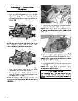
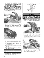
5. Loosen the cap screw on the end of the tensioner;

then remove the two cap screws securing the ten-
sioner adjuster assembly and remove the assembly.

Account for a gasket.

CC009D

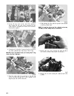
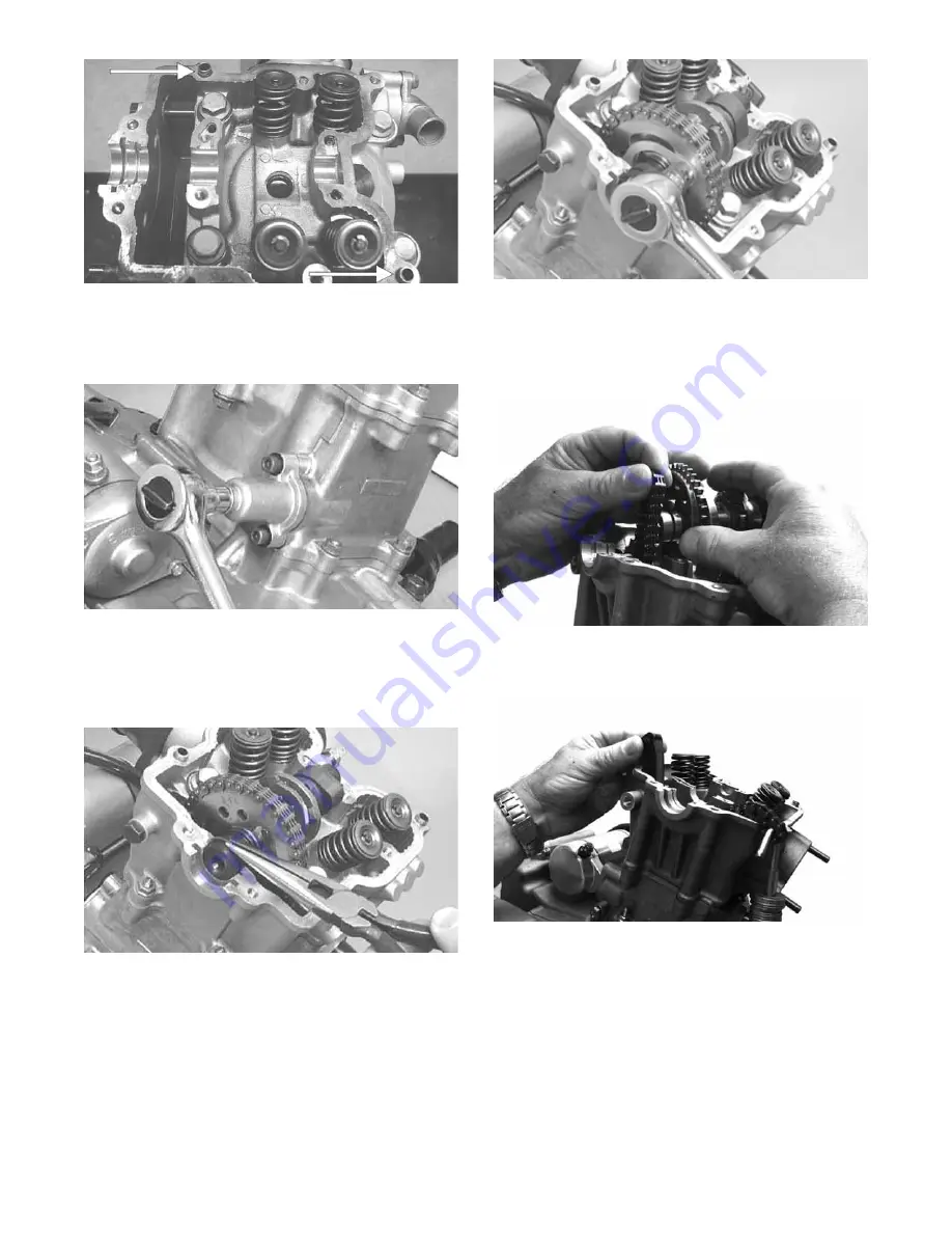
6. Using an awl, rotate the C-ring in its groove until it is

out of the cylinder head; then remove the C-ring.

NOTE: Care should be taken not to drop the C-ring

down into the crankcase.

CC012D

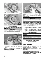
7. Bend the washer tabs down and remove the two cap

screws securing the sprocket to the camshaft; then
drop the sprocket off the camshaft.

CC013D

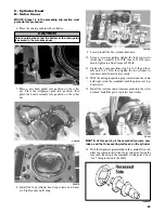
8. While holding the chain, slide the sprocket and camshaft

out of the cylinder head.

NOTE: Loop the chain over the cylinder and secure

it to keep it from falling into the crankcase.

FI620

9. Remove the cap screw securing the chain tensioner

(account for a washer); then remove the tensioner.

FI617

10. Remove the five nuts securing the cylinder head to the

cylinder.

Содержание PROWLER HDX 2015

Страница 1: ...S E R V I C E M A N U A L S E R V I C E M A N U A L S E R V I C E M A N U A L www arcticcat com PROWLER HDX...

Страница 2: ...ds Warning Caution Note and At This Point to emphasize important information The symbol WARNING identifies personal safety related information Be sure to fol low the directive because it deals with th...

Страница 3: ......

Страница 4: ...Removing Engine Transmission 38 Servicing Engine 500 41 Servicing Engine 700 79 Installing Engine Transmission 116 Fuel Lubrication Cooling 120 Throttle Body 120 Gas Tank 121 Gas Vent Hoses 123 Oil Fi...

Страница 5: ...AND RINGS 500 Piston Skirt Cylinder Clearance 0 025 0 055 mm Piston Diameter 8 mm from Skirt End 88 96 88 98 mm Piston Ring Free End Gap max 1st 2nd 11 6 mm 10 1 mm Bore x Stroke 89 0 x 71 2 mm Cylind...

Страница 6: ...nt Drive Flange 40 54 Front Engine Mounting Bracket Frame 45 61 Rear Engine Mounting BracketFrame 45 61 Engine Mounting Through Bolt Frame 40 54 Front Differential Frame Differential Bracket 38 52 Rea...

Страница 7: ...er 11 15 Valve Inspection Cover Cylinder Head Cover 8 11 Cam Chain Tensioner Cylinder 10 13 5 Magneto Cover Crankcase 8 11 Rear Driveline Output Drive Flange 20 27 Water Pump Cover Housing Magneto Cov...

Страница 8: ...moved to a warm area ft lb N m ft lb N m ft lb N m ft lb N m 1 1 4 26 35 4 51 69 4 76 103 4 2 2 7 27 36 7 52 70 7 77 104 7 3 4 1 28 38 1 53 72 1 78 106 1 4 5 4 29 39 4 54 73 4 79 107 4 5 6 8 30 40 8 5...

Страница 9: ...Store the vehicle indoors in a level position Preparation After Storage Taking the vehicle out of storage and correctly preparing it will assure many miles and hours of trouble free riding 1 Clean th...

Страница 10: ...255 Item Initial Service After Break In First Month or 100 Miles Every Day Every Month or Every 100 Miles Every 3 Months or Every 300 Miles Every 6 Months or Every 500 Miles EveryYear or Every 1500 Mi...

Страница 11: ...asteners and remove the air filter cover HDX050A 3 Remove the two screws securing the filter then remove the filter 4 Fill a wash pan larger than the element with a non flammable cleaning solvent then...

Страница 12: ...ve adjuster dial in place use the valve adjuster handle and loosen the jam nut then rotate the tappet adjuster screw clockwise until friction is felt C Align the valve adjuster handle with one of the...

Страница 13: ...f compression is now evident service the piston rings see the appropriate Engine Transmission Top Side Components Spark Plug A light brown insulator indicates that the plug is correct A white or dark...

Страница 14: ...e oil into a drain pan then remove the center console seat seat back and seat base PR078A 3 Using the Oil Filter Wrench and a ratchet handle or a socket or box end wrench remove the old oil filter NOT...

Страница 15: ...e vehicle on level ground 2 Remove each fill plug 3 Drain the lubricant into a drain pan by removing in turn the drain plug from each HDX255 HDX220A 4 After all the lubricant has been drained install...

Страница 16: ...the vehicle on a level floor so the headlights are approximately 6 1 m 20 ft from an aiming surface wall or similar aiming surface NOTE There should be an average operating load on the vehicle when ad...

Страница 17: ...oir If the level in the res ervoir is not above the MIN add DOT 4 brake fluid PR095 2 Depress the brake pedal several times to check for a firm brake If the brake is not firm the system must be bled T...

Страница 18: ...mage If found the brake hoses must be replaced CHECKING REPLACING PADS The clearance between the brake pads and brake discs is adjusted automatically as the brake pads wear The only maintenance that i...

Страница 19: ...t procedure 20 times until brake pads are bur nished Checking Replacing V Belt REMOVING 1 Remove the seat seat back and seat base then remove the floor and gas tank 2 Remove the cap screws securing th...

Страница 20: ...be removed 3 With the vehicle in neutral rotate the V belt and clutches counterclockwise until the V belt is flush with the top of the driven pulley 4 Place the CVT cover gasket into position then in...

Страница 21: ...leshoot the EPS system prior to replacing the EPS assem bly see the Electrical System section as there are several possible external causes for system fail ure 1 Support the vehicle on appropriate sta...

Страница 22: ...ible until the EPS is engaged with the coupler 3 Install the EPS assembly into the coupler turning the EPS shaft slightly to align the index spline then seat the EPS firmly onto the frame 4 Install fo...

Страница 23: ...Assembly in this section 2 Support the steering rack assembly in a suitable holding fixture or bench vise then cut the securing band and slide the boot toward the outer tie rod end 3 Using a punch or...

Страница 24: ...the steering rack assembly to the rack bracket and remove from the left side INSPECTING 1 Inspect the tie rod ends for damaged threads torn boots or excessive wear 2 Inspect the tie rods for bends or...

Страница 25: ...g pad ding or broken spokes 2 Inspect the splines for wear 3 Check that the steering wheel is not bent INSTALLING 1 Install the steering wheel aligning the two match marks then apply a drop of red Loc...

Страница 26: ...Assembly REMOVING With the upper steering shaft removed remove the cap screw from the intermediate shaft coupler and remove the shaft from the EPS and vehicle INSPECTING NOTE The lower steering shaft...

Страница 27: ...l 2 Remove the cotter pin from the axle 3 Remove the nut securing the hub 4 Remove the brake caliper 5 Remove the hub assembly 6 Remove the cotter pin from the tie rod end and remove the tie rod end f...

Страница 28: ...with red Loctite 271 Tighten to 30 ft lb then install a new cotter pin and spread the pin NOTE During assembling new cotter pins should be installed 4 Apply a small amount of grease to the hub splines...

Страница 29: ...G Dislodge the throttle cable holding grommet from the actuator arm then remove two torx head screws and nuts securing the accelerator pedal assembly to the splash panel and remove the accelerator ped...

Страница 30: ...shift arm stud then loosen the upper adjuster nut on the shift cable and remove the shift cable from the shifter assembly HDX166A HDX178A 3 Tilt the cargo box back and remove the E clip from the shift...

Страница 31: ...hen fully in Park See Periodic Maintenance Shift Lever LCD Gauge Indicator Lights REPLACING 1 Remove the steering wheel then remove the steering wheel boot 2 Remove the two machine screws securing the...

Страница 32: ...rear of the tire then using a tape measure measure and record the distance between the marks at the front and rear The front measurement should be 6 12 mm 1 4 1 2 in greater than the rear measurement...

Страница 33: ...t the four headlight connectors and remove two nylon ties PR328A 2 Loosen but do not remove the four cap screws and flange nuts securing the hood hinge to the frame then lower the hood PR332A 3 Finish...

Страница 34: ...he side foot restraints 3 Remove the center floorboard HDX132A 4 While pulling forward on the upper rear of the floor lift the rear part of the floor above the seat locating stud PR163 NOTE To aid in...

Страница 35: ...crews then install the steering shaft boot and steering wheel Apply a drop of red Loc tite 271 to the steering shaft then tighten the steering wheel nut to 25 ft lb and install the lock clip 4 Install...

Страница 36: ...r pivot housings with the holes in the cargo box then install the lower pivot housings and secure with the four shoulder cap screws Tighten to 20 ft lb 3 Raise the cargo box then connect the lift supp...

Страница 37: ...en 4 Frame distorted 5 Shock absorber defective 1 Adjust pressure 2 Adjust alignment 3 Replace bearings 4 Repair replace frame 5 Replace shock absorber Problem Steering impaired Condition Remedy 1 Tir...

Страница 38: ...first 10 hours or 200 miles are most critical to the life of this ROV Proper operation during this break in period will help assure maximum life and performance from the ROV Instruct the customer to f...

Страница 39: ...lace fuel injector 5 Adjust clearance Problem Engine noisy Excessive valve chatter Condition Remedy 1 Valve clearance excessive 2 Valve spring s weak broken 3 Rocker arm rocker arm shaft worn 4 Camsha...

Страница 40: ...y Condition Remedy 1 Engine oil overfilled contaminated 2 Piston rings cylinder worn 3 Valve guides worn 4 Cylinder wall scored scuffed 5 Valve stems worn 6 Stem seals defective 1 Drain excess oil cha...

Страница 41: ...gasline hose connector with a shop cloth then remove the gasline hose connector from the fuel rail HDX138A 6 Loosen the clamp securing the air filter intake tube to the air filter then remove the moun...

Страница 42: ...t to the engine case Remove the cap screw from the shift arm and disconnect the gear position switch connector Slide the gear position switch off the engine HDX254 HDX251 NOTE On the 500 shifting the...

Страница 43: ...ings at the muffler then remove the exhaust pipe Account for a grafoil seal in the cylinder head and a grafoil seal at the muffler HDX153A 16 Remove the cap screws securing the driveshafts to the fron...

Страница 44: ...e only those components which need to be addressed and to service only those components The technician should use discretion and sound judgment NOTE The engine transmission does not have to removed fr...

Страница 45: ...ve the cap screw from the tension adjuster then using a flat blade screwdriver relax the cam chain tension by rotating the adjuster screw clock wise until it locks FI607A FI608 4 Bend the washer tabs...

Страница 46: ...nd secure it to keep it from falling into the crankcase FI620 FI617A 7 Remove the cam chain tensioner pivot bolt and remove the chain tensioner then remove the two nuts securing the cylinder head to t...

Страница 47: ...alignment pins FI624A 13 Using an awl remove one piston pin circlip Take care not to drop it into the crankcase FI625 14 Using Piston Pin Puller remove the piston pin Account for the opposite side cir...

Страница 48: ...igure eight motion until a uniform bright metallic finish is attained CC130D Removing Valves NOTE Index all valves springs and cotters to their original position when removing When installing all valv...

Страница 49: ...the valve seals then place a lower spring seat and valve guide seal over each valve guide CC144D 2 Insert each valve into its original valve location 3 Install the valve springs with the painted end o...

Страница 50: ...t not exceed speci fications CC995 Measuring Piston Pin Connecting Rod Small End and Piston Pin Bore 1 Measure the piston pin outside diameter at each end and in the center If measurement does not mee...

Страница 51: ...d threads using a heli coil insert 3 Place the cylinder head on the surface plate covered with 400 grit wet or dry sandpaper Using light pressure move the cylinder head in a figure eight motion Inspec...

Страница 52: ...sh the cylinder in parts cleaning solvent 3 Inspect the cylinder for pitting scoring scuffing and corrosion If marks are found repair the surface using a 320 grit ball hone NOTE To produce the proper...

Страница 53: ...der pin should be flat side out with the weight retracted the unloader pin should be round side out CF060A 2 If damaged the camshaft must be replaced Installing Top Side Components A Piston B Cylinder...

Страница 54: ...e the head assembly into position on the cylinder making sure the cam chain is routed through the chain cavity MD1347 7 Install the four cylinder head cap screws with wash ers Note that the two cap sc...

Страница 55: ...the recessed side facing the camshaft lobes onto the camshaft and place it into posi tion with the cam chain over the sprocket CD463 MD1359 14 Place the C ring into position in its groove in the cyl...

Страница 56: ...he cylinder Tighten to 10 ft lb 22 Using a flat blade screwdriver turn the tensioner screw counterclockwise to apply tension to the cam chain then install the cap screw plug and washer and tighten sec...

Страница 57: ...moved from the frame for this procedure Removing Left Side Components A Water Pump B Speed Sensor C Magneto Cover Stator Assembly 1 Remove the coolant hose connecting the water pump to the cylinder th...

Страница 58: ...he rotor flywheel on the crankshaft and install the crankshaft protector FI549 8 Using the Magneto Rotor Remover Set break the rotor flywheel loose from the crankshaft then remove the puller and crank...

Страница 59: ...ate the gear counterclockwise and it should turn freely If it moves or locks up both ways the starter clutch must be replaced 2 Inspect the starter clutch gear for chipped or missing teeth or discolor...

Страница 60: ...rcumference then using a suitable bearing driver press the bearing from the gear FI583 2 Thoroughly clean the gear hub then apply a drop of green Loctite 620 to the bearing outer race and press into t...

Страница 61: ...Tighten securely 5 Install the upper cable hold down and secure with a cap screw Tighten securely FI595A REPLACING MAGNETO COVER BEARINGS 1 Using a suitable press and proper support press the bearing...

Страница 62: ...rankshaft then install the rotor flywheel key in the crankshaft FI551A 8 Install the rotor flywheel and secure with the nut Tighten to 107 ft lb C Magneto Cover D Water Pump NOTE Steps 1 8 in the prec...

Страница 63: ...scretion and sound judgment NOTE The engine transmission does not have to be removed from the frame for this procedure Removing Right Side Components A V Belt Cover B Driven Pulley C Clutch Cover 1 If...

Страница 64: ...face and spacer Account for the movable drive face rollers and outer drive face cover MD1035 MD1034 MD1036 5 Using a 6 mm cap screw threaded into the fixed driven face spread the driven pulley by tur...

Страница 65: ...en pull it away from the right side crankcase half Account for two alignment pins and gasket MD1115 D Centrifugal Clutch Assembly E Oil Pump Drive Gear F Oil Pump Driven Gear NOTE Steps 1 10 in the pr...

Страница 66: ...nt for the drive pin and thrust washer MD1020 G Oil Pump Oil Strainer NOTE Steps 1 17 in the preceding sub sections must precede this procedure 18 Remove three cap screws holding the oil pump and remo...

Страница 67: ...ONE WAY DRIVE 1 Place the one way clutch onto the clutch shoe assembly with the green dot or the word OUTSIDE directed away from the clutch shoe KC330 2 Place the clutch housing onto the clutch shoe o...

Страница 68: ...e Phillips head screws securely MD1337 2 Place the strainer cap into position on the crankcase making sure the O ring is properly installed and secure with the four cap screws Tighten the cap screws t...

Страница 69: ...s the clutch shoe 8 Install the one way clutch making sure that the green dot or the word OUTSIDE is directed away from the crankcase MD1286 B Clutch Cover C Fixed Drive Face D Movable Drive Face NOTE...

Страница 70: ...until the faces open sufficiently to allow the V belt to drop into the pulley approximately 3 4 in KC137 NOTE The arrows on the V belt should point in direction of engine rotation 15 Making sure the m...

Страница 71: ...Side Left Side and Right Side must precede this procedure NOTE For efficiency it is preferable to remove and disassemble only those components which need to be addressed and to service only those com...

Страница 72: ...noting the location of the front and rear bearing locating pins and the center bearing locating ring FI660A FI659A FI661A 2 Remove the reverse idler assembly B Account for and note the location of th...

Страница 73: ...ning nut From inside the crankcase using a rubber mallet drive out the output shaft assembly Account for the output shaft a shim a washer and the nut Servicing Center Crankcase Components SECONDARY GE...

Страница 74: ...rement is within tolerance Note the following chart Checking Tooth Contact NOTE After correcting backlash of the second ary driven bevel gear it is necessary to check tooth contact 1 Remove the second...

Страница 75: ...suring Connecting Rod Big End Side to Side 1 Push the lower end of the connecting rod to one side of the crankshaft journal 2 Using a feeler gauge measure the gap between the connecting rod and cranks...

Страница 76: ...gear washer then remove the low driven gear along with the bearing and bushing FI666 FI667 4 Remove the splined washer then remove the circlip securing the high low sliding dog Remove the slid ing do...

Страница 77: ...asher 1 on the countershaft install the high driven gear bushing 3 bearings 2 and gear 4 on the countershaft then install the washers 5 and secure with the snap ring FI671A FI670 2 Install the high lo...

Страница 78: ...NOTE The countershaft assembly is now ready to be installed Assembling Crankcase Half NOTE For ease of assembly install components on the right side crankcase half NOTE If the output shaft was removed...

Страница 79: ...te the crankshaft so the counterweight is toward the rear of the engine Install the crank balancer shaft MD1024 5 Install the key in the crank balancer shaft then install the gear and aligning the tim...

Страница 80: ...FI653A FI655A 9 Install the input driveshaft FI646 10 Install the spacer 1 shaft 2 reverse idler gear and washer 3 FI641A FI645 11 Install the secondary output driveshaft assembly into the crankcase...

Страница 81: ...TE Rotate the shafts back and forth to ensure no binding or sticking occurs while tightening the cap screws MD1008 4 From the left side install the remaining crankcase cap screws then tighten only unt...

Страница 82: ...ngine transmission does not have to removed from the frame for this procedure Removing Top Side Components A Valve Cover Rocker Arms B Cylinder Head Camshaft NOTE Remove the spark plug and timing insp...

Страница 83: ...ring down into the crankcase CC012D 7 Bend the washer tabs down and remove the two cap screws securing the sprocket to the camshaft then drop the sprocket off the camshaft CC013D 8 While holding the...

Страница 84: ...e 13 Loosen the clamp securing the coolant hose to the union then detach the hose 14 Remove the two nuts securing the cylinder to the crank case CC023D 15 Lift the cylinder off the crankcase taking ca...

Страница 85: ...the piston while rotating it out of the groove Servicing Top Side Components VALVE ASSEMBLY When servicing valve assembly inspect valve seats valve stems valve faces and valve stem ends for pits burn...

Страница 86: ...1 Insert a snap gauge 1 2 way down into each valve guide bore then remove the gauge and measure it with a micrometer 2 Acceptable inside diameter range must be within specifications 3 If a valve guide...

Страница 87: ...essive blowby indicates worn piston rings or an out of round cylinder Removing Piston Rings 1 Starting with the top ring slide one end of the ring out of the ring groove CC400D 2 Remove each ring by w...

Страница 88: ...g expander 4 in the bottom groove of the piston then install the thin oil rings 3 over the expander making sure the expander ends do not overlap Stagger the end gaps of the upper and lower thin oil ri...

Страница 89: ...tion must not exceed specifications CC141D Cleaning Inspecting Cylinder 1 Wash the cylinder in parts cleaning solvent 2 Inspect the cylinder for pitting scoring scuffing warpage and corrosion If marks...

Страница 90: ...after honing using soap and hot water Dry with compressed air then immediately apply oil to the cylinder bore If the bore is severely damaged or gouged replace the cylinder CC390D 4 If any measurement...

Страница 91: ...espect to the crankcase CF083 3 Lubricate the inside wall of the cylinder then using a ring compressor or the fingers compress the rings and slide the cylinder over the piston Route the cam chain up t...

Страница 92: ...ft lb 11 Tighten the 8 mm nuts from step 9 to 21 ft lb and the 6 mm nuts to 8 5 ft lb then tighten the two cylinder to crankcase nuts from step 4 securely 12 With the timing inspection plug removed an...

Страница 93: ...ng surface D Recessed side of the sprocket directed toward the cam lobes E Camshaft alignment pin and sprocket alignment hole smallest are aligned 17 Place the tab washer onto the sprocket making sure...

Страница 94: ...e screw bottoms CD501 NOTE The adjuster shaft will be drawn into the ten sioner as the adjuster screw is rotated clockwise The adjuster shaft tension will be released in step 25 24 Place the chain ten...

Страница 95: ...ghten the cap screws from step 29 to 8 5 ft lb 31 Adjust valve tappet clearance see Periodic Mainte nance 32 Place the two tappet covers into position making sure the proper cap screws are with the pr...

Страница 96: ...over tube from the cylinder head Account for an O ring 5 Remove the two cap screws securing the water pump to the engine then remove the water pump 6 Remove the cap screws securing the left side cover...

Страница 97: ...pin into the crankcase 13 Remove the shift shaft noting the timing marks for assembling purposes Account for two washers PR430A 14 Remove the gear shift cam plate and account for a washer then remove...

Страница 98: ...cap screws after applying a drop of red Loctite 271 to the threads Tighten to 26 ft lb using a crisscross pattern Make sure the one way bearing is installed with the notches directed away from the ro...

Страница 99: ...for and note the position of the harness hold down under the crankshaft position sensor FI590 3 Install the new stator coil assembly and secure with three new patch lock cap screws Tighten to 15 ft lb...

Страница 100: ...e gears are secured remove the oil passage plug from the crankcase 3 Install the two starter gear shafts then install the two starter gears with the beveled side of the intermedi ate gear facing inwar...

Страница 101: ...resh engine oil then place it into position on the two alignment pins Make sure the outer shift shaft washer is in place PR431A 9 Install the magneto cover and secure with the cap screws Tighten only...

Страница 102: ...ly those components which need to be addressed and to service only those components The technician should use discretion and sound judgment NOTE The engine transmission does not have to be removed fro...

Страница 103: ...screws securing the clutch cover Note the location of the different lengthed cap screws for installing purposes Using a rubber mallet carefully remove the cover Account for two align ment pins CD973A...

Страница 104: ...the fixed drive spacer CF085 CC596 NOTE Account for and inspect the clutch housing seal CF088A 10 Remove the two cap screws securing the gear posi tion switch then remove the switch 11 Remove the nut...

Страница 105: ...f the gear for installing purposes Account for a pin and a washer CD984 CD895A 15 Using an impact driver remove the three torx head screws securing the oil pump then remove the pump CD988 Servicing Ri...

Страница 106: ...The driven pulley is a nonserviceable com ponent If the pulley faces cam ramps or sheave bushing are worn or loose the pulley must be replaced as an assembly Do not disassemble the driven pulley Inst...

Страница 107: ...lush with each other 5 Install the clutch shoe assembly and secure with the flange nut threads coated with red Loctite 271 Tighten to 221 ft lb PR410A 6 Install the clutch cover alignment pins into th...

Страница 108: ...position and secure with the nut Tighten to 162 ft lb CF262 13 Slide the fixed drive face onto the clutch shaft 14 Spread the faces of the driven pulley by threading a cap screw into one of the bosse...

Страница 109: ...hould use discretion and sound judgment Separating Crankcase Halves 1 Remove the right side cap screws securing the crankcase halves Note the location of the different lengthed cap screws 2 Remove the...

Страница 110: ...E677A 5 Remove the countershaft assembly D Account for a washer on each end of the countershaft CC674 NOTE Do not disassemble the countershaft assem bly unless necessary If necessary see Servicing Cen...

Страница 111: ...count for shim shims NOTE Shims should be measured and kept for a starting point in adjusting backlash Servicing Center Crankcase Components SECONDARY OUTPUT DRIVE GEARS Initial Set Up NOTE If the sec...

Страница 112: ...a tions in both directions Gear contact should extend from the root to the top of the gear teeth MT016A 6 To adjust tooth contact use the following chart to correctly shim the driven shaft 7 After cor...

Страница 113: ...the upper connecting rod small end bore then remove the gauge and measure it with micrometer CC290D 2 Maximum diameter must not exceed specifications Measuring Connecting Rod Small End Deflection 1 P...

Страница 114: ...ing the positions for assembling then remove the high driven gear outer washer high driven gear high driven gear bearing high driven gear bushing and high driven gear inner washer GZ283A 2 Remove the...

Страница 115: ...he washer and gear GZ314 5 Remove the reverse driven washer then remove the low driven gear locking washer GZ320 GZ319 GZ318A 6 Remove the low driven gear Account for a bearing bushing and thrust wash...

Страница 116: ...19B GZ320B 3 Install the reverse driven bushing and bearing then install the reverse driven gear GZ286A GZ287 4 Install the outer reverse driven washer then secure the reverse driven gear assembly wit...

Страница 117: ...ing the countershaft assembly account for the washer on each end of the shaft Assembling Crankcase Half 1 Install the secondary drive gear assembly into the crankcase MT014 2 Apply a liberal amount of...

Страница 118: ...Place a washer on each end of the countershaft assembly then install the assembly CC674 7 Place a washer on the end of the gear shift shaft then install the shaft assembly making sure the two holes o...

Страница 119: ...install the case half 6 mm cap screws then tighten only until snug NOTE Rotate the shafts back and forth to ensure no binding or sticking occurs 7 From the right side install the 6 mm cap screws then...

Страница 120: ...O2 sensor and tighten the sensor to 19 ft lb Connect the harness to the sensor 7 Install the forward exhaust pipe heat shield and secure with the machine screws Tighten securely HDX152A 8 Install the...

Страница 121: ...boot with the clamp and tighten securely HDX148A 14 Connect the IAT sensor connector to the IAT sen sor and the crankcase breather tube to the crank case then install the air filter intake tube and se...

Страница 122: ...e When clear coolant flows tighten the bleed screw HDX158B 18 Connect the negative battery cable to the battery 19 Install the center skid plate center floorboard and seat base then install the seat b...

Страница 123: ...n switch to the OFF position then remove the ignition switch key 2 Remove the seat seat back and seat base then dis connect the battery 3 Remove the air inlet boot between the air filter and throttle...

Страница 124: ...or pedal to Wide Open Throttle WOT 2 Place the ignition key in the ON position and wait for 10 seconds 3 Release the accelerator pedal and wait an additional 10 seconds 4 Turn the key to the OFF posit...

Страница 125: ...the fuel level sensor for proper operation see Electric Fuel Pump Fuel Level Sensor in this sec tion INSTALLING 1 Place the gas tank into position in the vehicle then install the inside rear hold down...

Страница 126: ...est 1 Remove the seat seat back and seat base 2 Using a suitable T fitting connect Oil Pressure Test Kit to the oil fitting and hose Tighten all clamps securely NOTE Some oil seepage may occur when in...

Страница 127: ...n the bleed screw on the thermostat housing to allow air to bleed from the cooling system When clear coolant no bubbles is pres ent tighten the bleed screw securely then fill the cooling system to the...

Страница 128: ...connect the cooling fan wire connector to the main harness PR183A 3 Open the high point bleed screw on the thermostat housing to allow trapped air to escape Tighten securely after filling 4 Pour the r...

Страница 129: ...the radiator 2 Remove the fan assembly from the radiator INSTALLING 1 Position the fan assembly on the radiator then secure with existing hardware NOTE The fan wiring must be in the upper right posit...

Страница 130: ...filled air pockets may develop therefore run the engine for five minutes after the initial fill shut the engine off and then fill the cooling system 5 Check the entire cooling system for leakage 6 Ins...

Страница 131: ...ided with the battery or battery maintainer charger Loss of battery charge may be caused by ambient temper ature ignition OFF current draw corroded terminals self discharge frequent start stops and sh...

Страница 132: ...e the charger connected to the battery for a minimum 1 hour after the Maintenance Charge Indicator D illuminates If the battery becomes hot to the touch stop charging Resume after it has cooled 7 Once...

Страница 133: ...ing the diagnostic mode on the LCD gauge see EFI Diagnostic System in this sec tion 1 Connect the meter leads selector in OHMS position to the sensor terminals 2 Suspend the sensor and a thermometer i...

Страница 134: ...ery voltage from one side of the connector terminal ends NOTE Battery voltage will be indicated from only one side of the fuse holder connector terminal the other side will show no voltage NOTE When t...

Страница 135: ...e OHMS position 2 Connect the red tester lead to the brown wire then connect the black tester lead to the white wire The meter reading must be 104 156 ohms AC Voltage NOTE The battery must be at full...

Страница 136: ...F the meter should read approximately 2 9 DC volts NOTE If the meter does not read as specified replace the sensor Speed Sensor NOTE Prior to testing the speed sensor inspect the three wire connector...

Страница 137: ...D Override 7000 Differential Lock Override Component data and system updates can be retrieved performed using the CATT II Navigate the screens as required Code Fault Description Fault Condition Possib...

Страница 138: ...mal C1316 EEPROM Error EPS internal memory error has been detected Internal EPS condition Correct EPS condition C1317 CAN Bus Error The EPS has lost CAN communication with the EFI ECM Broken CAN wires...

Страница 139: ...then select the high beam position on the headlight switch The meter must show battery voltage 4 Connect the red meter lead to either of the two white wires then select the low beam position on the he...

Страница 140: ...ive Actuator NOTE With the engine stopped and the ignition switch in the ON position a momentary whirring sound must be noticeable each time the drive select switch is moved to 2WD and 4WD Test the sw...

Страница 141: ...is defective it must be replaced REMOVING 1 Disconnect the battery 2 Remove the nut securing the positive cable to the starter then remove the cable from the starter 3 Remove the two cap screws secur...

Страница 142: ...tep 4 4 Disconnect the two wire plug from the starter relay then connect the red tester lead to the green wire and the black tester lead to the black wire PR297A 5 Depress the starter button and obser...

Страница 143: ...om the fuel pump 4 Mark the fuel pump mounting and gas tank for installing purposes then remove the screws securing the fuel pump to the gas tank and remove the fuel pump 5 Using duct tape or other su...

Страница 144: ...y Try to verify all other charging system components before the regulator rectifier is replaced TESTING VOLTAGE 1 Start engine and warm up to normal operating tempera tures then connect a multimeter s...

Страница 145: ...r components To verify ignition timing use the following procedure NOTE To check ignition timing the seat seat back and seat base must be removed 1 Attach the Timing Light to the spark plug high ten s...

Страница 146: ...and right observing the meter The meter should read 4 0 8 0 DC volts 700 or 3 0 7 0 DC volts 500 after approximately one second in the tilted position If the meter readings are not as specified the ti...

Страница 147: ...ON position and wait for 10 seconds 3 Release the accelerator pedal and wait an additional 10 seconds 4 Turn the key to the OFF position and allow the gauge to shut off EFI Diagnostic System DIGITAL G...

Страница 148: ...red by the ECT sensor DTC P0116 P0117 P0118 P0119 Usage Monitor coolant temperature to verify the following 1 ECT sensor signal 2 High Temperature indicator on 230 degrees F 3 Thermostat opening appro...

Страница 149: ...CM CAN signal to EPS unit TPS tPS Diagnostic Mode EFI007 Display of TPS 0 closed 95 100 WOT DTC P0121 P0122 P0123 Usage Verify TPS signal and adjust throttle cable MAP bArO Diagnostic Mode EFI006 Disp...

Страница 150: ...hassis ground Correct condition P0030 O2 Heater Intermittent Open Heater or interconnect harness intermittent or open Correct condition P0031 O2 Heater Low SG Heater or interconnect harness shorted to...

Страница 151: ...ery power Correct condition P0485 Fan Primary Right Relay Control Circuit Low SG Open Primary fan fuse has blown the primary fan relay has been removed or interconnect harness shorted to chassis groun...

Страница 152: ...place battery Problem Magneto overcharges Condition Remedy 1 Battery short circuited 2 Regulator rectifier defective 3 Regulator rectifier poorly grounded 1 Replace battery 2 Replace regulator rectifi...

Страница 153: ...ach time the drive select switch is shifted If no sound is heard see the Electrical System section If the actuator runs constantly or makes squealing or grinding sounds the actuator must be replaced R...

Страница 154: ...with a nylon cable tie Front Differential REMOVING 1 Remove the belly panel then place the vehicle on jack stands adjusted high enough to allow working from the underside of the vehicle NOTE The jack...

Страница 155: ...allow it to drop or hang 11 Remove the lower shock cap screws Account for the lock nuts then move the shocks and upper A arm up and secure them with a strap PR200 12 Push the axle shaft toward the di...

Страница 156: ...ormed on a rear gear case 1 Using a T 40 torx wrench remove the cap screws securing the pinion housing GC004A 2 Using a rubber mallet remove the housing Account for a gasket Remove the fork collar and...

Страница 157: ...input shaft seal making sure it is fully seated in the edge of the housing GC014 3 Lubricate the input shaft with High Performance 2 Molybdenum Disulphide Grease packing the boot ribs and splines the...

Страница 158: ...ing the pinion housing Account for the coupler fork and spring differential only GC015 2 Using a T 40 torx wrench remove the cap screws securing the differential cover Account for and make note of the...

Страница 159: ...er assembly Account for shim s and mark as right side KX179 KX181 Disassembling Pinion Gear 1 Remove the internal snap ring securing the pinion bearing in the housing WC430 2 Using the Pinion Gear Sha...

Страница 160: ...side directed away from the bearing WC429 Shimming Procedure Shim Selection It is very important to adjust bevel gears for the proper running tolerances Gear life and gear noise are greatly affected b...

Страница 161: ...install a thicker shim and recheck GC036A 3 Install the bearing flange onto the gear case cover making sure the alignment locating pin engages the locating hole in the cover then make sure the bear in...

Страница 162: ...ver side up then install a dial indicator contacting the ring gear axle flange GC035 2 Zero the dial indicator then push the ring gear toward the dial indicator and release End play should be 0 004 0...

Страница 163: ...d with green Loctite 270 Account for the ID tag Tighten the cap screws evenly to 23 ft lb NOTE Grease can be applied to the O ring for ease of assembling NOTE If a new housing is being installed tight...

Страница 164: ...nut Do not tighten at this time 2 Install the lower differential mounting cap screw washers and lock nut Note the correct location for the washers PR205A 3 Tighten the nuts to 38 ft lb 4 Pour 275 ml 9...

Страница 165: ...ts Tighten to 200 ft lb then install new cotter pins PR256 12 Install the wheels and tighten in 20 ft lb increments to 40 ft lb steel wheel or 80 ft lb aluminum wheel 13 Remove the vehicle from the su...

Страница 166: ...a front drive axel see Front Differential in this section CLEANING AND INSPECTING AXLES NOTE Always clean and inspect the drive axle com ponents to determine if any service or replacement is necessar...

Страница 167: ...be used to replace the out board boot NOTE In the outboard boot use the final 40 grams 1 3 of contents of grease from the pack in the bear ing housing INSTALLING REAR DRIVE AXLE 1 Push the axle shaft...

Страница 168: ...tep 3 to 200 ft lb then install and spread a new cotter pin making sure each side of the pin is flush to the hub nut CD027 7 Install the wheel and tighten in 20 ft lb increments to 40 ft lb steel whee...

Страница 169: ...ar with selected shim into the cover and measure the ring gear to thrust button clearance with a thickness gauge Clearance should be 0 002 0 004 in GC058A 3 If clearance is as specified remove the rin...

Страница 170: ...shaft housing onto the rear drive gear case and secure with the three cap screws Tighten to 23 ft lb INSTALLING 1 Slide the gear case into position down through the upper left side of the frame then...

Страница 171: ...caliper front only PR243A 5 Remove the hub assembly 6 Remove the four cap screws securing the brake disc PR254A CLEANING AND INSPECTING 1 Clean all hub components 2 Inspect all threads for stripping o...

Страница 172: ...el and tighten in 20 ft lb increments to 40 ft lb steel wheel or 80 ft lb aluminum wheel 7 Remove the vehicle from the support stand Hydraulic Brake Caliper REMOVING DISASSEMBLING 1 Secure the vehicle...

Страница 173: ...e caliper opposite the O ring side and remove the outer brake pad then remove the inner brake pad NOTE If brake pads are to be returned to service do not allow brake fluid to contaminate them PR237A P...

Страница 174: ...the piston surface for scoring discoloration or evidence of binding or galling 5 Inspect the caliper holder for wear or bending ASSEMBLING INSTALLING 1 Install new seals into the brake caliper housing...

Страница 175: ...e from the support stand and ver ify brake operation MASTER CYLINDER ASSEMBLY NOTE The master cylinder is a non serviceable component it must be replaced as an assembly Removing 1 Slide a piece of fle...

Страница 176: ...sed by removing the belly panel To remove the belly panel see the Steering Frame Controls section 1 Support the vehicle on suitable jack stands elevated high enough to allow working from the underside...

Страница 177: ...aring cup then remove the yoke from the separator tool NOTE Repeat steps 2 3 for the opposite side bear ing cup 4 Remove the separator tool from the vise and install the universal joint bearing cups a...

Страница 178: ...Replace coupling 4 Replace joint 5 Replace gear s 6 Replace gears pinions 7 Replace fuse drive select switch front drive actuator Problem Braking poor Condition Remedy 1 Pad worn 2 Brake fluid leaking...

Страница 179: ...retainer and remove the spring CF341 CLEANING AND INSPECTING 1 Clean all shock absorber components in parts clean ing solvent 2 Inspect each shock rod for nicks pits rust bends and oily residue 3 Insp...

Страница 180: ...p then bleed the air from the air chamber FS141 2 While holding the end cap unscrew the air cham ber FS142 3 Drain the oil from the air chamber FS143 4 Remove the air chamber from the bottom of the sh...

Страница 181: ...emove the shock rod piston assembly from the shock body FS151 12 Drain the oil from the shock body into a suitable con tainer 13 Using an appropriate floating piston removal tool remove the floating p...

Страница 182: ...e to vent the shock body FS156 4 Using Fox Racing Shock Oil fill the shock body to the bottom of the threads then allow to sit 1 2 min utes to ensure no air is in the oil FS157 5 Lubricate the O ring...

Страница 183: ...the bleed ball and set screw into the bearing cap FS162 FS163 10 Charge the shock with nitrogen to 200 psi FS164 11 Using a 3 16 in Allen wrench tighten the nitrogen bladder FS165 12 Install the air...

Страница 184: ...hand tight FS171 NOTE Prior to installing the air chamber make sure the end cap O ring is properly positioned in the chamber 19 Invert the shock and secure by the end cap to assure the air chamber is...

Страница 185: ...the nut securing the hub 4 Remove the brake caliper Account for two cap screws CD007 5 Remove the hub assembly 6 Remove the cotter pin and slotted nut securing the tie rod end to the knuckle then rem...

Страница 186: ...1 Apply Loctite Primer T to the A arm socket then apply green Loctite 609 to the entire outside diame ter of the ball joint Install the ball joint into the A arm and secure with the snap ring AF616D...

Страница 187: ...the hub nut from step 9 to the shaft axle Tighten to 200 ft lb 12 Install a new cotter pin and spread the pin to secure the nut NOTE If the cotter pin cannot be inserted due to misalignment of the ho...

Страница 188: ...en only at this time 2 Slide the knuckle onto the drive axle and into position on the A arms then secure the knuckle to the A arms with cap screws and new lock nuts Tighten to 35 ft lb 3 Tighten the h...

Страница 189: ...heel CHECKING INFLATING 1 Using an air pressure gauge measure the air pressure in each tire Adjust the air pressure as necessary to meet the recommended inflation pressure 2 Inspect the tires for dama...

Страница 190: ...ated bushings worn 1 Adjust preload 2 Replace bushing Problem Suspension noisy Condition Remedy 1 Cap screws suspension system loose 2 A arm related bushings worn 1 Tighten cap screws 2 Replace bushin...

Страница 191: ...188 NOTES...

Страница 192: ...Printed in U S A Trademarks of Arctic Cat Inc Thief River Falls MN 56701 p n 2260 410...

Отзывы: