141
ATV2116
NOTE: If readings are erratic, clean the resistor
wiper and resistor with clean alcohol and retest. If
still not correct, replace the fuel level sensor.
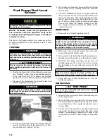
4. To replace the fuel level sensor, use the following
procedure.
A. Disconnect the two-wire connector (A); then
press the fuel level sensor toward the top of the
fuel pump to release it from the mounting slot
(B).
FI460A
B. Engage the tabs (C) of the fuel level sensor into
the mounting slot (B) and press toward the bottom
of the fuel pump to latch in place; then connect
the two-wire connector (A).
INSTALLING
1. Place the fuel pump assembly into the gas tank with
a new gasket aligning the match marks; then secure
with the four screws. Tighten securely.
NOTE: It is important to install the fuel pump with
the correct orientation to ensure adequate float
lever clearance.
2. Connect the gasline hose to the fuel pump pipe and
secure with the hose clamp; then connect the electri-
cal plug to the main harness.
3. Connect the negative battery cable; then turn the
ignition switch to the ON position and verify that no
gas leaks are present, the pump runs for 2-3 seconds,
and the gas gauge reading is normal.
4. Start the engine to verify proper engine operation;
then shut off the engine and install the seat base, seat
back, and seat.
Regulator/Rectifier
The regulator/rectifier is located under the seat next to the
battery. Try to verify all other charging system components
before the regulator/rectifier is replaced.
TESTING VOLTAGE
1. Start engine and warm up to normal operating tempera-
tures; then connect a multimeter (set at the DC Voltage
position) to the battery as follows.
2. Connect the red tester lead to the positive battery post
and the black tester lead to the negative battery post.
3. Slowly increase RPM. The voltage should increase with
the engine RPM to a maximum of 15.5 DC volts.
NOTE: If voltage rises above 15.5 DC volts, the regu-
lator is faulty or a battery connection is loose or cor-
roded. Clean and tighten battery connections or
replace the regulator/rectifier. If voltage does not rise,
replace the regulator/rectifier.
Headlights
The connectors are the four 2-prong ones secured to the
headlight bulbs (two on each side).
VOLTAGE
NOTE: The low beams are the outside bulbs (black
and white wires) and the high beams are the inside
bulbs (yellow and black wires). Always connect the
black tester lead to the black wires. The ignition
switch must be in the ON position.
1. Set the meter selector to the DC Voltage position.
2. Set the light switch to the correct position for the
affected light; then connect the black tester lead to the
black wire using a MaxiClip.
3. Connect the red tester lead to the yellow wire (high
beam) or white wire (low beam) using a MaxiClip. The
meter must show battery voltage.
NOTE: If battery voltage is not shown in any test,
inspect the LIGHTS fuse on the power distribution
module, headlight switch, ignition switch, switch
connectors, or wiring harness.
Содержание PROWLER HDX 2015
Страница 3: ......
Страница 191: ...188 NOTES...
Страница 192: ...Printed in U S A Trademarks of Arctic Cat Inc Thief River Falls MN 56701 p n 2260 410...


