136
Ignition Switch
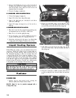
To access the ignition switch, dash switches, front acces-
sory connectors, and front switched accessory connector,
the dash must be unfastened and slid to the rear.
VOLTAGE
NOTE: Perform this test on the harness connector.
1. Set the meter selector to the DC Voltage position.
2. Connect the red meter lead to the red wire; then con-
nect the black meter lead to battery ground.
3. Meter must show battery voltage.
NOTE: If the meter shows no battery voltage,
troubleshoot the main 30 amp fuse, the battery, or
the main wiring harness.
4. Connect the red meter lead to the red/black wire;
then with the black lead grounded, turn the ignition
switch to the ON position. The meter must show bat-
tery voltage.
5. Connect the red meter lead to the yellow/green wire;
then with the black lead grounded, turn the ignition
switch to the START position. The starter should
engage and the meter must show battery voltage.
NOTE: When the starter is engaged, battery volt-
age will be approximately 10.5 DC volts.
Headlight Switch
VOLTAGE
1. Connect the red meter lead to the gray wire; then
connect the black meter lead to the black wire.
2. Turn the ignition switch to the ON position. The
meter must show battery voltage.
NOTE: If the meter does not show battery volt-
age, troubleshoot the LIGHTS fuse on the power
distribution module, the ignition switch, or the
main harness.
3. Connect the red meter lead to the yellow wire; then
select the high beam position on the headlight
switch. The meter must show battery voltage.
4. Connect the red meter lead to either of the two white
wires; then select the low beam position on the head-
light switch. The meter must show battery voltage.
NOTE: The battery voltage will show lower in steps
3 and 4 due to electrical loading of the headlights.
Drive Select Switch
RESISTANCE
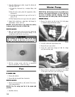
1. Remove the switch assembly from the dash; then dis-
connect the harness from the switch.
NOTE: The switch can be removed from the dash
using a thin, flat pry bar or suitable putty knife. It is not
necessary to remove the dash to remove the switch.
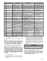
2. Using an ohmmeter, the following readings must be
observed.
PR566A
VOLTAGE
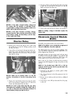
NOTE: Voltage tests must be made with the
switch and the actuator connected. The meter can
be connected at the actuator connector using a
break-out harness or MaxiClips.
1. Connect the black tester lead to the black wire; then
turn the ignition switch to the ON position.
2. Select the DC Volts position on the tester and
observe the meter readings for each of the three
switch positions.
Component data can be retrieved using the CATT II. Uti-
lize the Sensor Data screen.
2WD
4WD
DIFFERENTIAL LOCK
A to D <1 ohm
A to D <1 ohm
A to D <1 ohm
C to E <1 ohm
C to E <1 ohm
C to E <1 ohm
A to B Open
A to B <1 ohm
A to B <1 ohm
A to C Open
A to C Open
A to C <1 ohm
A to E Open
A to B <1 ohm
A to C <1 ohm
WIRE COLOR
2WD
4WD
DIFFERENTIAL LOCK
Black to Orange 12.0 DC Volts 12.0 DC Volts
12.0 DC Volts
Black to White/
Green
11.5 DC Volts
0 DC Volts
0 DC Volts
Black to White/
Red
11.5 DC Volts 11.5 DC Volts
0 DC Volts
Содержание PROWLER HDX 2015
Страница 3: ......
Страница 191: ...188 NOTES...
Страница 192: ...Printed in U S A Trademarks of Arctic Cat Inc Thief River Falls MN 56701 p n 2260 410...


