6-21
6
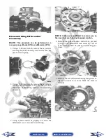
3. Secure the differential to the frame with two
through-bolts and secure with lock nuts and flat
washers. Tighten to 38 ft-lb.
4. Install the rear drive axles (see Drive Axles in this
section).
5. Install the driveline brake caliper and tighten the
mounting cap screws to 20 ft-lb; then adjust the
parking brake (see Parking Brake in Section 2).
6. Fill the differential (XTX) or gear case
(Prowler/XT) with the appropriate lubricant.
Hub
REMOVING
1. Secure the vehicle on a support stand to elevate the
wheel; then remove the wheel.
NOTE: Removing or tightening of the hub nuts
requires that the axles be locked. To lock the rear
axle, set the parking brake. To lock the front axle,
turn the ignition switch to ON, select 4WD on the
2WD/4WD drive selector switch, and engage the
differential lock; then set the parking brake and
turn the ignition switch to OFF.
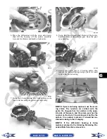
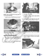
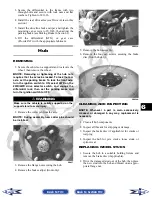
2. Remove the cotter pin from the axle.
NOTE: During assembly, new cotter pins should
be installed.
PR257
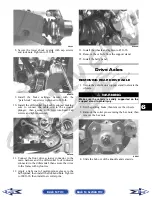
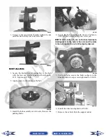
3. Remove the flange nut securing the hub.
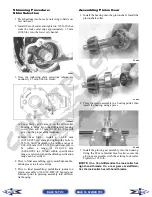
4. Remove the brake caliper (front only).
PR243A
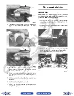
5. Remove the hub assembly.
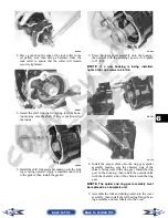
6. Remove the four cap screws securing the brake
disc (front hub only).
PR254A
CLEANING AND INSPECTING
NOTE: Whenever a part is worn excessively,
cracked, or damaged in any way, replacement is
necessary.
1. Clean all hub components.
2. Inspect all threads for stripping or damage.
3. Inspect the brake disc (if applicable) for cracks or
warping.
4. Inspect the hub for pits, cracks, loose studs, or
spline wear.
REPLACING WHEEL STUDS
1. Secure the hub in a suitable holding fixture and
remove the brake disc (if applicable).
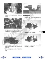
2. Drive the damaged stud out of the hub; then place
the new stud into the hub and thread on an appro-
priate flange nut.
! WARNING
Make sure the vehicle is solidly supported on the
support stand to avoid injury.
Back to TOC
Back to Section TOC
Next
Back


