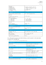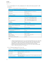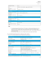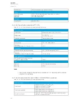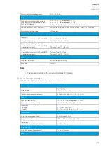
9.2.1.16 Overpower (P>; 32O), underpower (P<; 32U) and reverse power (Pr; 32R)
protection
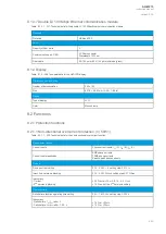
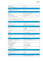
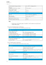
Table. 9.2.1.16 - 324. Technical data for the power protection functions.
Measurement inputs
Current inputs
Phase current inputs: I
L1
(A), I
L2
(B), I
L3
(C)
Voltage inputs
U
L1
, U
L2
, U
L3
U
L12
, U
L23
, U
L31
(+ U
0
)
Calculated measurement
Three-phase active power
Pick-up
P>
Prev>
0.10…150 000.00 kW, setting step 0.01 kW
-15 000.00…-1.00 kW, setting step 0.01 kW
P<
Low-power blocking P
SET
<
0.00…150 000.00 kW, setting step 0.01 kW
0.00…100 000.00 kW, setting step 0.01 kW
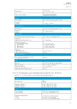
Inaccuracy:
- Active power
Typically <1.0 %P
SET
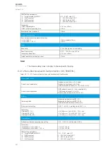
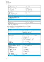
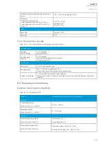
Operation time
Definite time function operating time setting
0.00…1800.00 s, setting step 0.005 s
Inaccuracy:
- Definite time (P
M
/P
SET
ratio 1.05
→
)
±1.0 % or ±35 ms
Instant operation time
Start time and instant operation time (trip):
- P
M
/P
SET
ratio 1.05
→
<50 ms
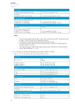
Reset
Reset ratio
97 or 103 %P
SET
Reset time setting
Inaccuracy: Reset time
0.000…150.000 s, step 0.005 s
±1.0 % or ±35 ms
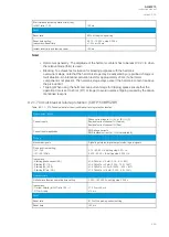
Instant reset time and start-up reset
<50 ms
No
Notte!
e!
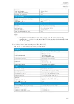
• Voltage measurement starts from 0.5 V and current measurement from 50 mA. In case either
or both are missing the power measurement is forced to 0 kW. If the settings allow it (low-
power blocking = 0 kW), the P< might be in the trip state during this condition. The trip is
released when the function begins to measure the voltage and the current again.
• When the low-power blocking is set to zero, it is not in use. Also, all power measurements
below 1.00 kW are forced to zero ("P< blocked").
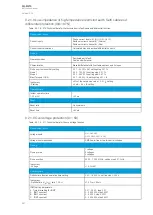
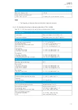
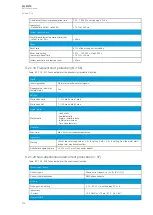
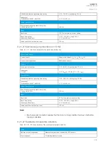
9.2.1.17 Power protection (P, Q, S>/<; 32)
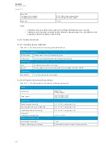
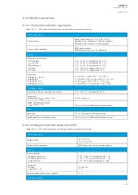
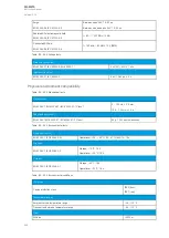
Table. 9.2.1.17 - 325. Technical data for the power protection function.
Measurement inputs
Current inputs
Phase current inputs: I
L1
(A), I
L2
(B), I
L3
(C)
Voltage inputs
U
L1
, U
L2
, U
L3
U
L12
, U
L23
, U
L31
(+ U
0
)
Calculated measurements
Three-phase active, reactive or apparent power (P, Q or S) value based on the chosen or
set nominal amplitude.
Pick-up
A
AQ
Q-M215
-M215
Instruction manual
Version: 2.04
453
Содержание AQ-M215
Страница 1: ...AQ M215 Motor protection IED Instruction manual ...
Страница 410: ...Figure 7 4 242 Example block scheme A AQ Q M215 M215 Instruction manual Version 2 04 409 ...
Страница 432: ...Figure 8 14 265 Panel cutout dimensions and device spacing A AQ Q M215 M215 Instruction manual Version 2 04 431 ...
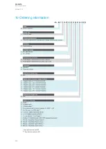
Страница 466: ...10 Ordering information A AQ Q M215 M215 Instruction manual Version 2 04 465 ...


