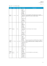
Name
Range
Step Default
Protection
functions
Description
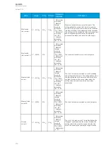
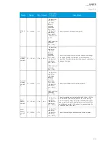
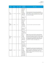
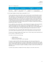
Safe stall
time hot
0.1…600.0s
0.1s
15.0s
- Motor status
monitoring
- Frequent start
protection (N>;
48)
- Machine
thermal
overload
protection
(Tm>; 49M)
- Motor start
monitoring
(Ist>; 48/14)
- Mechanical
jam protection
(Im>; 51M)
The safe stall time when the motor is hot. This setting value is
used for the hot thermal stall curve selection in automatic
control. This parameter is also used in the motor start-up and
the number of starts calculations.
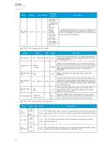
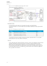
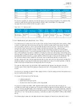
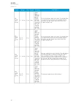
Table. 5.3.20 - 159. Settings of the Ist> function.
Name
Range
Step
Default
Description
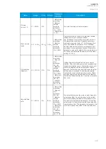
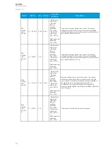
Starting time
0.000…1800.000s 0.005s 0.040s
Motor starting time the user sets. This setting should include the
expected normal starting time of the protected motor as well as
the operating marginal.
Definite time or
I
2
t
0: Definite
1: I
2
t mode
-
0:
Definite
Selection of the operating mode. If the I
2
t mode is selected, the
function monitors the heating effect as a function of the measured
current. In the Definite time mode, the function only monitors the
start/stall signal duration and compares it to the "Starting
time" setting.
Speed switch in
use
0: No
1: Yes
-
0: No
Selection of whether or not the speed switch is used in the
application.
Speed SW wait
time
0.000…1800.000s 0.005s 0.040s
The setting which determines how long the function waits for the
speed switch to give a signal since the starting of the motor. If the
speed switch is not activated during this set time, the starting of
the motor is halted. This setting is visible only if the "Speed switch
in use" setting is active.
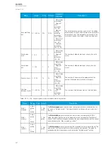
Speed SW NO/
NC
0: NO
1: NC
-
0: NO
The polarity of the speed switch signal, normally open ("NO") or
normally closed ("NC"). This setting is visible only if the "Speed
switch in use" setting is active.
Operating mode 0: Starts only
1: Starts and stall
-
0:
Starts
only
Operating mode selection of the function. This setting defines
whether the function monitors only the start-up conditions of the
motor, or both the start-up and stall conditions of the motor.
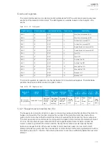
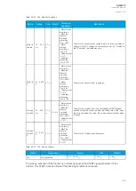
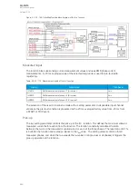
Table. 5.3.20 - 160. Output signals of the Ist> function.
Name
Range Step Default
Description
Ist>
START
0: Not
active
1:
Active
-
0: Not
active
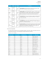
The START output of the function. This signal activates when the starting conditions
are met and the function is about to initiate a trip after the time calculation is finished.
Ist> TRIP
0: Not
active
1:
Active
-
0: Not
active
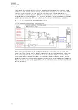
The TRIP output of the function. This signal activates when the pick-up and time
conditions are met.
Ist>
BLOCKED
0: Not
active
1:
Active
-
0: Not
active
The BLOCKED output of the function. This signal activates when the START output is
activated but the function is blocked from operating normally.
A
AQ
Q-M215
-M215
Instruction manual
Version: 2.04
233
Содержание AQ-M215
Страница 1: ...AQ M215 Motor protection IED Instruction manual ...
Страница 410: ...Figure 7 4 242 Example block scheme A AQ Q M215 M215 Instruction manual Version 2 04 409 ...
Страница 432: ...Figure 8 14 265 Panel cutout dimensions and device spacing A AQ Q M215 M215 Instruction manual Version 2 04 431 ...
Страница 466: ...10 Ordering information A AQ Q M215 M215 Instruction manual Version 2 04 465 ...

