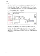
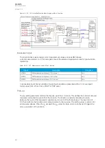
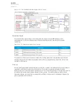

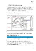

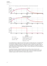

Figure. 5.3.23 - 164. Simplified function block diagram of the Im> function.
Measured input
The function block uses analog current measurement values and uses RMS phase current
measurements. A -20 ms averaged value of the selected magnitude is used for pre-fault data
registering.
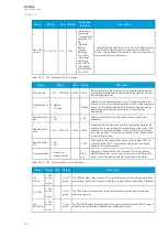
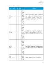
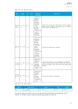
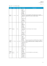
Table. 5.3.23 - 173. Measurement inputs of the Im> function.
Signal
Description
Time base
IL1RMS
RMS measurement of phase L1 (A) current
5ms
IL2RMS
RMS measurement of phase L2 (B) current
5ms
IL3RMS
RMS measurement of phase L3 (C) current
5ms
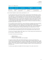
The selection of the used AI channel is made with a setting parameter. In all possible input channel
variations the pre-fault condition is presented with a 20 ms averaged history value from -20 ms from
a START or TRIP event.
Pick-up
The
I
set
setting parameter controls the pick-up of the Im> function. This defines the maximum allowed
measured current before action from the function. The function constantly calculates the ratio
between the
I
set
and the measured magnitude (
I
m
) for each of the three phases. The reset ratio of 97 %
is built into the function and is always relative to the
I
set
value. The setting value is common for all
measured phases, and when the
I
m
exceeds the
I
set
value (in single, dual or all phases) it triggers the
pick-up operation of the function.
A
AQ
Q-M215
-M215
Instruction manual
Version: 2.04
245
Содержание AQ-M215
Страница 1: ...AQ M215 Motor protection IED Instruction manual ...
Страница 410: ...Figure 7 4 242 Example block scheme A AQ Q M215 M215 Instruction manual Version 2 04 409 ...
Страница 432: ...Figure 8 14 265 Panel cutout dimensions and device spacing A AQ Q M215 M215 Instruction manual Version 2 04 431 ...
Страница 466: ...10 Ordering information A AQ Q M215 M215 Instruction manual Version 2 04 465 ...