5.3.24 Power factor protection (PF<; 55)
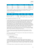
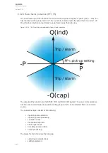
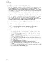
The power factor protection function is the ratio of active power to apparent power (cos φ = P/S). In a
fully resistive load the power factor is 1.00. In partially inductive loads the power factor is under 1.00.
Power factor protection cannot detect a power factor value that is too low.
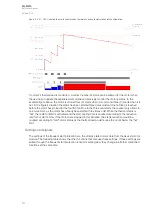
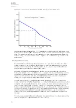
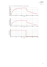
Figure. 5.3.24 - 165. Operating characteristics of power factor protection.
The outputs of the function are the START, TRIP and BLOCKED signals. The power factor protection
function uses a total of eight (8) separate setting groups which can be selected from one common
source.
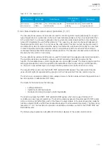
The operational logic consists of the following:
• input magnitude selection
• input magnitude processing
• saturation check
• threshold comparator
• block signal check
• time delay characteristics
• output processing.
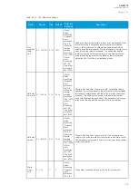
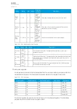
The inputs for the function are the following:
• operating mode selections
• setting parameters
A
AQ
Q-M215
-M215
Instruction manual
Version: 2.04
251
Содержание AQ-M215
Страница 1: ...AQ M215 Motor protection IED Instruction manual ...
Страница 410: ...Figure 7 4 242 Example block scheme A AQ Q M215 M215 Instruction manual Version 2 04 409 ...
Страница 432: ...Figure 8 14 265 Panel cutout dimensions and device spacing A AQ Q M215 M215 Instruction manual Version 2 04 431 ...
Страница 466: ...10 Ordering information A AQ Q M215 M215 Instruction manual Version 2 04 465 ...

