

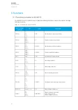
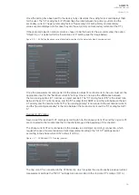

CT module
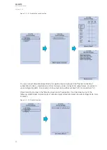
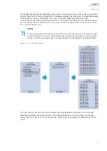
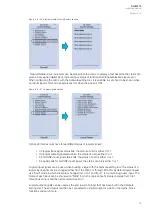
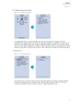
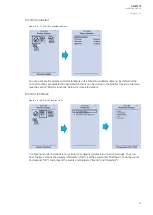
Figure. 4.7 - 42. CT module section.
The three main sections ("Phase CT scaling", "Residual I01 CT scaling" and "Residual I02 CT scaling")
determine the ratio of the used transformers. Additionally, the nominal values are also determined in
the
CT module submenu. Sometimes a mistake in the wiring can cause the polarity to be changed; in
such cases, you can invert the polarity of each phase current individually. The
CT module submenu
also displays additional information such as CT scaling factors and per-unit scaling factors.
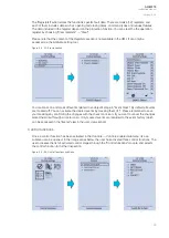
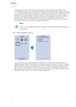
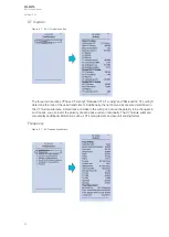
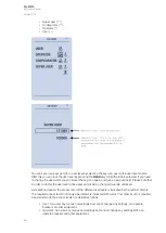
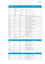
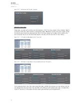
Frequency
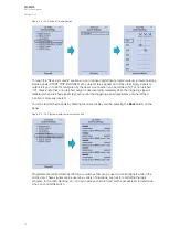
Figure. 4.7 - 43. Frequency submenu.
A
AQ
Q-M215
-M215
Instruction manual
Version: 2.04
43
Содержание AQ-M215
Страница 1: ...AQ M215 Motor protection IED Instruction manual ...
Страница 410: ...Figure 7 4 242 Example block scheme A AQ Q M215 M215 Instruction manual Version 2 04 409 ...
Страница 432: ...Figure 8 14 265 Panel cutout dimensions and device spacing A AQ Q M215 M215 Instruction manual Version 2 04 431 ...
Страница 466: ...10 Ordering information A AQ Q M215 M215 Instruction manual Version 2 04 465 ...