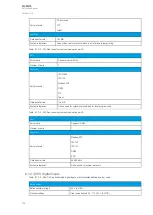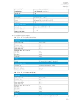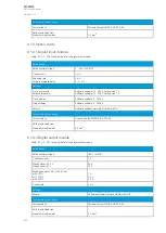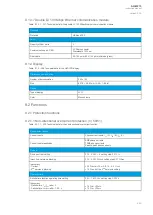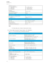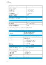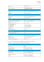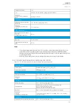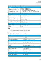
IDMT setting parameters:
- k Time dial setting for IDMT
- A IDMT constant
- B IDMT constant
- C IDMT constant
0.01…25.00, step 0.01
0…250.0000, step 0.0001
0…5.0000, step 0.0001
0…250.0000, step 0.0001
Inaccuracy:
- IDMT operating time
- IDMT minimum operating time
±1.5 % or ±20 ms
±20 ms
Instant operation time
Start time and instant operation time (trip):
- I
m
/I
set
ratio > 3
- I
m
/I
set
ratio = 1.05…3
<40 ms (typically 30 ms)
<50 ms
Reset
Reset ratio:
- Current
- U1/I1 angle
97 % of the pick-up current setting
2.0°
Reset time setting
Inaccuracy: Reset time
0.010…10.000 s, step 0.005 s
±1.0 % or ±50 ms
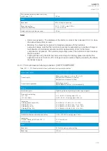
Instant reset time and start-up reset
<50 ms
No
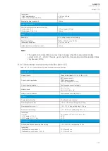
Notte!
e!
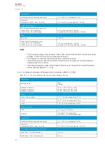
• The minimum voltage for direction solving is 1.0 V secondary. During three-phase short-
circuits the angle memory is active for 0.5 seconds in case the voltage drops below 1.0 V.
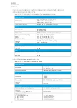
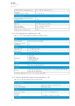
9.2.1.4 Directional earth fault protection (I0dir>; 67N/32N)
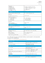
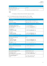
Table. 9.2.1.4 - 312. Technical data for the directional earth fault function.
Measurement inputs
Current input (selectable)
Residual current channel I
01
(Coarse)
Residual current channel I
02
(Fine)
Calculated residual current: I
L1
(A), I
L2
(B), I
L3
(C)
Current input magnitudes
RMS residual current (I
01
, I
02
or calculated I
0
)
TRMS residual current (I
01
or I
02
)
Peak-to-peak residual current (I
01
or I
02
)
Voltage input (selectable)
Residual voltage from U3 or U4 voltage channel
Residual voltage calculated from U
L1
, U
L2
, U
L3
Voltage input magnitudes
RMS residual voltage U
0
Calculated RMS residual voltage U
0
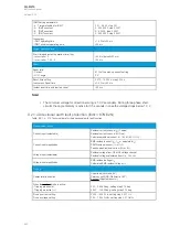
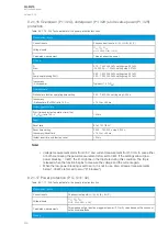
Pick-up
Characteristic direction
Unearthed (Varmetric 90°)
Petersen coil GND (Wattmetric 180°)
Earthed (Adjustable sector)
When the
earthed mode is active:
- Tripping area center
- Tripping area size (+/-)
0.00…360.00 deg, setting step 0.10 deg
45.00…135.00 deg, setting step 0.10 deg
Pick-up current setting
Pick-up voltage setting
0.005…40.00 × I
n
, setting step 0.001 × I
n
1.00…75.00 %U0
n
, setting step 0.01 %U0
n
A
AQ
Q-M215
-M215
Instruction manual
Version: 2.04
443
Содержание AQ-M215
Страница 1: ...AQ M215 Motor protection IED Instruction manual ...
Страница 410: ...Figure 7 4 242 Example block scheme A AQ Q M215 M215 Instruction manual Version 2 04 409 ...
Страница 432: ...Figure 8 14 265 Panel cutout dimensions and device spacing A AQ Q M215 M215 Instruction manual Version 2 04 431 ...
Страница 466: ...10 Ordering information A AQ Q M215 M215 Instruction manual Version 2 04 465 ...

