background image

ANGELUS SANITARY CAN MACHINE COMPANY

SERVICE NOTICE

1 of 5

Complete Oil Change, 180S Seamer

The following procedure will drain all oil from the 180S seamer to insure all contami-

nates have been removed before new oil is installed.

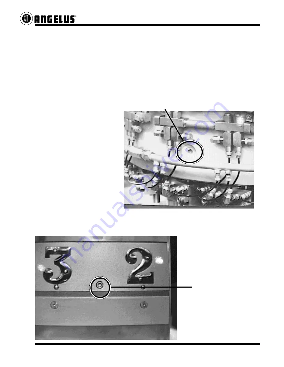
A.  Drain oil from the Upper Turret. Take out the Drain Plug located at

station no.1

NOTE:

Each Seaming Spindle is
held into the Upper Turret by a
Bearing Retainer with Face Seal.
Bearing cavities will hold some
oil and not allow a full drain. Three
and 1/2 quarts will drain from the
Turret. It holds six quarts.

B.  Drain Lower Turret.

Oil in the Lower Turret can be completely drained by taking out (6) pipe plugs located

between stations 2 & 3, 5 & 6, 8 & 9, 11 & 12, 14 & 15, and 17 & 18.

1/8 -27 pipe plugs are at this

location around the Lower

Turret.

11/10/90-18000002

Содержание 180S

Страница 1: ... 001 Subdivision related to the part 14 which will continually increase as the number of Lubrication Notices are created Type of part Main Division such as 14 for Lubrication or 44 for Shafts or 00 for an assembled component Designates Seamer Model Number Revisions to existing Service Notices will be as follows The File Name will be duplicated on the Service Notice with the latest revision level d...

Страница 2: ...ming Roll Lever Torque Specifications Seaming Lever Cone Point Set Screw number 32S826 used to locate the Seaming Roll Lever on the Seaming Lever Shaft should be tightened to 80 ft lbs 80 ft lbs 80 ft lbs 80 ft lbs 80 ft lbs before endplay adjustments are made Locknut number 104S816 used to clamp hold the Seaming Roll Adjustment Screw should be tightened to approx 45 ft lbs 45 ft lbs 45 ft lbs 45 ...

Страница 3: ... the Drain Plug located at station no 1 NOTE EachSeamingSpindleis heldintotheUpperTurretbya BearingRetainerwithFaceSeal Bearingcavitieswillholdsome oilandnotallowafulldrain Three and1 2quartswilldrainfromthe Turret Itholdssixquarts B Drain Lower Turret Oil in the Lower Turret can be completely drained by taking out 6 pipe plugs located between stations 2 3 5 6 8 9 11 12 14 15 and 17 18 1 8 27 pipe...

Страница 4: ...en cleaning out the Housing area it is very important to not use high pressure hoses or any forced cleaning solutions inside this area Water will enter the Upper Turret settling into bearing cavities and will not be drained out through the plug If this accidently happens all 18 Seaming Spindles will have to come out to drain water D Turn off air pressure supply to the Drive Case before disconnecti...

Страница 5: ...E NOTICE 3 of 5 F Drain oil from Filler Gear Drive Case Take out a 3 4 pipe plug under the Filler Drive Clutch Housing Take out a 1 2 pipe plug on the bottom of this Drive Case E Drain Drive Case Remove 1 pipe plug from the Drive Case Cover ...

Страница 6: ...OTICE 4 of 5 G Drain In Motion Timer and Tail Shaft Assemblies Two 3 4 pipe plugs located under each of these H Replace Filtration System Filter Clean out Filter canister and install new Filter Drain oil reservoir and Clean out Water Separator ...

Страница 7: ...oil 4 Filler Drive and In Motion Timer Housings will hold 4 1 2 quarts Aero Shell W80 oil Both these units can be filled at the same time through an opening in the Filler Drive Clutch Housing 5 Fill Tail Shaft assembly with 1 quart of Aero Shell W 80 oil There is a fill plug on top of this assembly 5 Refill Filler Drive Gear Case with 3 quarts of 80 90W Lubriplate Fill plugs are located on top of ...

Страница 8: ...ANGELUS SANITARY CAN MACHINE COMPANY SERVICE NOTICE 8 31 04 18000003 Model 180S Seaming Rolls with Ceramic Ball Bearing Assembly InstallationRequirements ...

Страница 9: ...uire one shot of grease from a hand grease gun for each assembly If more than one shot of grease is installed the ceramic ball bearing will expel excess grease out of the assembly Suggestedlubricationintervals every72hoursw N L G I TypeOgreaseor1shotofgreaseaftersanitationtoremovewater fromtheSeamingRoll Seaming Roll with Ceramic BearingAssembly Installation Sequence for 180S Seamers ...

Страница 10: ...ravity Feed Lubricator solenoid is programmed to operate during Jog or Run commands only Availability Available for purchase per Parts List 121LM158 03 Installation Procedure Divert the existing Y Feed Sprocket Line into P Lower Chuck Cam Line Use Pipe Thread Compound PST on all connections Remove lines Y and P and temporary identify lines Y or P See Fig 1 Remove straight fittings from the base Se...

Страница 11: ...otice Fig 1 180S without Gravity Feed Lubricator Fig 2 180S without Gravity Feed Lubricator Fig 3 180S with Gravity Feed Lubricator Fig 4 180S with Gravity Feed Lubricator P Lower Chuck Cam Line Y Feed Sprocket Line Plugged Feed Sprocket Line Line Diversion P Lower Chuck Cam Line Y Feed Sprocket Line ...

Страница 12: ...Angelus 4900 Pacific Blvd Los Angeles CA 90058 2214 Tel 323 583 2171 3 5 18014001 11 7 05 Service Notice Fig 5 Lube Line Diversion Ref Data Sheet G180 156 A ...

Страница 13: ...Angelus 4900 Pacific Blvd Los Angeles CA 90058 2214 Tel 323 583 2171 4 5 18014001 11 7 05 Service Notice Fig 6 Lubricator Assembly Ref Data Sheet G180 156 A ...

Страница 14: ...Angelus 4900 Pacific Blvd Los Angeles CA 90058 2214 Tel 323 583 2171 5 5 18014001 11 7 05 Service Notice Fig 7 262S854 Feed Sprocket Guard Modification Ref Data Sheet G180 156 A ...

Страница 15: ...Angelus 4900 Pacific Blvd Los Angeles CA 90058 2214 Tel 323 583 2171 5 5 18014001 11 7 05 Service Notice Fig 7 262S854 Feed Sprocket Guard Modification Ref Data Sheet G180 156 A ...

Страница 16: ...customers responsibility to install the oil seal filler gear box applications only Description Filler Gear Box Applications The oil seal 26S815 located within the 17S843 clutch housing prevents intermixing of the filler gear box gear lube and clutch housing tailshaft seamer oil Filler Belt Drive Applications The oil seal 26S815 is not to be installed because it would restrict seamer oil to the fil...

Страница 17: ...xture is designed to be used with the Carrier in or out although the Torquing Fixture Flange is more stable with the Carrier out of the bore when applying this amount of torque 2 Install the Nut Clamp using 4 M4 x 16mm L Soc Hd Screws Use Blue 243 Loctite on the screw threads 3 After tightening the Locknut install Bearing Retainer 76S817 always use Parker Super Lube on O Rings ensure that the oil ...

Страница 18: ...lla style Knockout Pads 1st Insure that the Lower Chuck Cam is located correctly the Lower Chuck Plate plane is within tolerance and the Seamer Pin Height is correct 2nd Measure the countersink depth on several covers Example 270 3rd Measure the Knockout Pad contact area of the cover on the same set of covers Average these dimensions Example 155 Countersink depth measurement of cover Knockout Pad ...

Страница 19: ...Seaming Turret around with a seamed can and correct internal pressure and Adjust Knockout Pad height stop at the point where the seamed can has with an Inside Micrometer just released from the Seaming Chuck Position the Knockout Cam Discharge radially until a 010 feeler gauge slips between the can and Lower Chuck Plate Secure the Cam NOTE Set Knockout Pads measuring from Lower Chuck Plate up to th...

Страница 20: ... DESIGNED FOR MAINTENANCE ON THE SEAMER AND NOT TO BE USED FOR PRODUCTION OR FOR CLEARING CAN JAMS IMPORTANT NOTICE LIMITER DEVICES ROTATION OF THE VARIATOR CAN BE LOCKED OUT IN EITHER DIRECTION REVERSE DIRECTION IS LOCKED OUT AT THE FACTORY AND ONLY MOTOR DIRECTION ALLOWS REVERSE ACTION TO USE ROTATION LIMITERS 1 ADJUST THE VARIATOR TO THE REQUIRED MAXIMUM SPEED OR TO ZERO R P M IF A DIRECTION OF...

Страница 21: ...vel side facing down 2 Press Ball Bearing ball loading groove facing up into place and install top Retaining Ring bevel side down Seat Retaining Ring with hammer punch 3 Push Bearing Holder into Assembly and install Snap Ring This Side Up stamping location 4 Snap Ring grooves are bevelled on the bottom when assembled correctly NOTE This Gear will Only be sold with the Ball Bearing and Retaining Ri...

Страница 22: ...ller Drive between Seamer and Filler 2 Operate Seamer at desired speed exam 2000 CPM 3 Actvate Seamer Brake by pushing an Emergency Stop Button 4 Observe number of stations that pass a given point after the stop button is pushed 5 Adjust Seamer Brake to stop Seamer after 16 stations pass 1RH Brake Rheostat located in the Electrical Console 6 Activate Filler Drive Clutch use Handwheel to re engage ...

Страница 23: ...section Please change the first sentence of the second paragraph following the NOTE to read When re engaging the Electric Clutch the Variable Speed Inching Mecha nism is used Note We don t feel that re engagement at 96 cans per minute max Inching Speed capabillity will damage internal parts Other wise we would suggest a speed in this case All instructions from this date on will have this informati...

Страница 24: ...6 2 M16 X 110mm Full thread Hex Hd Capscrews 2 M16 Full Nuts 4 M16 X 50mm L Hex Hd Capscrews 4 M16 Flat Washers A Install Sub Base Support Pads using M24 Full Nuts B Move the Sub Base into position under the Brake Housing and install M16 X 50mm Hex Hd capscrews and Flat Washers C Install M16 Full Thread Hex Hd Capscrews with Nuts through the Sub Base flange NOTE These jack screws along with the Su...

Страница 25: ...oles and Support Pad screws to allows room for Coupling installation zero this in There should be approximately 5 8 of an inch between the end of the Motor shaft and the Main Drive Shaft for Coupling installation or removal Dial Indicator Setup Adjustment Parameters Parts Required Dial Indicator with needle or plunger Strap Clamp or Magnetic Base Mount A Attach a dial indicator and strap clamp a m...

Страница 26: ...th readings can be performed using two dial indicators mounted on the strap clamp at the same time C Secure all Sub Base flange screws and Support Pad Nuts Dial set for aligning the Face Reading D Place the dial indicator needle on the front machined face of the Brake Housing Move the Motor on the Sub Base angularly until alignment is within 005 of an inch all around the face surface Secure Motor ...

Страница 27: ...3004 1 of 14 Rev 1 9 9 99 Model 180S Seamer System Operation and Control Logic Oil Lubrication System Optional Seaming Roll Grease System Variable Speed Inching Mechanism Filler Drive Seamer Safety Clutch No Can No Cover System Dual Speed Undercover Gassing System ...

Страница 28: ...ASTER DIVIDER VALVE AND IS INPUT TO THE SEAMER PLC OIL FILTRATION SYSTEM GENERAL INFORMATION THE OIL FILTRATION SYSTEM IS EMPLOYED AS A MEANS OF REMOVING WATER AND PARTICULATE MATTER FROM THE OIL IN THE SEAMER BASE ADDING OIL TO KEY WEAR POINTS IN A QUANTUM AMOUNT BOOSTING AND PROVIDING A MEANS OF TRABON RESERVOIR AUTOMATIC REFILL FROM THE SEAMER BASE OIL SUPPLY FILTRATION SYSTEM INFORMATION NOTE ...

Страница 29: ...ESERVOIR THE LOW OIL SWITCH IS SET TO ACTIVATE 3 5 INCHES ABOVE THE EMPTY RESERVOIR MARK WHICH WILL GIVE A 2 62 OIL HEEL 74 15 CU IN THIS CONVERTS TO A 53 MIN RUN INTERVAL BEFORE THE TRABON RESERVOIR IS COMPLETELY EMPTY THE HIGH OIL SWITCH IS SET TO ACTIVATE 7 5 AB0VE THE LOW OIL LEVEL SWITCH WHICH TRANSLATES TO 211 85 CU IN OF OIL OR 2 5 HOURS OF RUN TIME BE TWEEN THE HIGH OIL LEVEL SWITCH BEING ...

Страница 30: ...LAN STATES OF THE MASTER DIVIDER VALVE SECTION FOR PROPER CYCLING THE CYCLE MONITOR PROXIMITY IS PLC INPUT TO TWO 2 TIMERS ONE TIMES THE IN STATE AND THE OTHER TIMES THE OUT STATE OF THE MASTER DIVIDER VALVE PIN SHOULD EITHER TIMER TIME OUT THE PLC PROGRAM WILL COAST THE SEAMER TO A STOP OIL SYSTEM FAILURE LIGHT RED PILOT LIGHT WHICH INDICATES A TOTAL FAILURE OF THE TRABON OIL LUBRICATION SYSTEM B...

Страница 31: ...TE AS LONG AS THE PB IS DEPRESSED OIL LUBRICATION SYSTEM OIL PUMP PUSH ON PUSH OFF BUTTON GREEN ILLUMINATED PUSH BUTTON WHICH STARTS THE OIL FILTRATION PUMP WHEN HELD IN THIS PB MUST BE HELD IN UNTIL THE OIL FLOW SWITCH SENSES OIL FLOW AT WHICH TIME THE PLC WILL LATCH THE PUSH BUTTON LIGHT ON INDICATING THE PUMP IS IN OPERATION AND THE BUTTON CAN BE RELEASED IF THE OIL FILTRATION PUMP IS IN OPERAT...

Страница 32: ... SET TO OPEN IF THE OIL PRESSURE AT THE PUMP OUTLET SHOULD REACH 75 PSI HIGH OIL PRESSURE SWITCH N C CONTINUED THIS SWITCH WILL ACTUATE IF THE OIL FILTRATION SYSTEM IS ALLOWED TO OPERATE TO THE POINT WHERE THE FILTERS BECOME DIRTY AND ARE NOT REPLACED AT ACTUATION THE CHANGE FILTERS LIGHT WILL BECOME ILLUMINATED WARNING OIL PRESSURE SWITCH N C PRESSURE SWITCH LOCATED IN THE OIL FILTRATION SYSTEM P...

Страница 33: ...ON SYSTEM TIMERS TO MONITOR FAULT INTERVALS AND SEAMER CONTROL SYSTEM RESPONSE TIMES PLC ON DELAY TIMERS SHALL BE EMPLOYED AS FOLLOWS LAMP FLASHER TWO FREE RUNNING ON DELAY TIMERS WITH ONE TIMER RESETTING THE OTHER TIME BASE 0 01 SEC PRESET 30 3 SEC N O DONE BIT PROGRAMED TO CAUSE THE PLC LAMP OUTPUT TO TURN ON AND OFF AT A 3 SEC RATE NOTE LAMP FLASHER TIMERS ARE USED BY ALL SEAMER SYSTEM PROGRAMM...

Страница 34: ...ERVAL IS CHANGED TO SEVENTY TWO 72 HOURS VACUUM SYSTEM OPERATION WHEN A GREASE COMMAND IS INITIATED BY THE PLC PROGRAM THE CYCLE WILL START AS LONG AS THE SEAMER IS IN OPERATION THE VACUUM PUMP WILL TURN ON BY THE VALVE BEING ENERGIZED THE TIME THE VACUUM PUMP IS ON IS PRESET IN THE PLC AND THIS WILL BE ENOUGH TIME TO SUCK OR PULL THE OLD GREASE FROM THE SEAMING ROLL THE OLD GREASE WILL BE DEPOSIT...

Страница 35: ... WILL BE INITIATED BUT WITHOUT THE VACUUM CYCLE MANUAL GREASE BUTTON OPERATION LOCATED ON THE LUBE ENCLOSURE DOOR IS AN MANUAL LUBE BUTTON PRESSING THIS BUTTON WILL INITIATE ONE GREASE CYCLE WITH THE VACUUM CYCLE PRE WASH AND POST WASH OPERATION THIS LOGIC IS INCLUDED TO ENSURE THAT THE SEAMING ROLLS HAVE ADEQUATE GREASE PRIOR TO AND AFTER THE SEAMER IS IN WASHED DOWN BOTH OPERATIONS INITIATE TWO ...

Страница 36: ...THE LOGIC FOR INCHING FROM THE PENDANT STATION THE INCH MOTOR WILL BE RUNNING IN THE DIRECTION CHOSEN ONCE THE INCH BUTTON IS PRESSED THERE IS A SHORT TIME DELAY BEFORE THE CLUTCH WILL ENGAGE THE PRESET BUTTON ON THE OPERATOR INTERFACE IS USED FOR WHEN THE FILLER DRIVE CLUTCH IS DISENGAGED AND THAT THE SEAMER HAS NOT BEEN ROTATED THE LOGIC WILL ENABLE THE INCH CLUTCH TO ENERGIZE SO THE FILLER DRIV...

Страница 37: ...LL ENABLE THE INCHING LOGIC AND WILL DISABLE THE MAIN DRIVE CIRCUIT WHEN THE CLUTCH IS TO BE MANUALLY ENGAGED EITHER THE CLUTCH PRESET BUTTON ON THE OPERATOR INTERFACE OR THE CLUTCH ON OFF SELECTOR ON THE PENDANT WILL ENABLE THE INCH CIRCUIT IN THE EVENT THAT THE CLUTCH IS DISENGAGED WHILE RUNNING THE SEAMER THIS WILL ENABLE THE BRAKE CIRCUIT AND SHUT THE SEAMER DOWN IN A BRAKE STOP PLC LOGIC ALSO...

Страница 38: ...ENABLED BY THE PLC OUTPUT FOR THAT PARTICULAR COVER FEED SEPARATOR NO CAN NO COVER CONTROL LOGIC OPERATION THE LOGIC TO DO THE SWITCHING OF THE PROXIMITY SENSOR INPUTS AND PROVIDE AN OUTPUT TO THE COVER FEED SOLENOIDS ARE PROGRAMMED IN THE PLC THE SYSTEM REQUIRES THAT WE USE AN INTERRUPT ROUTINE IN THE PLC THE FLAG SENSOR INPUT IS WIRED TO A FAST RESPONSE INPUT MODULE THE FLAG PROXIMITY SENSOR INP...

Страница 39: ... SLOW SPEED THE LOW SPEED SOLENOID IS ENERGIZED WHEN OPERATING IN THE HIGH SPEED MODE BOTH HIGH AND LOW SPEED SOLENOIDS ARE ENERGIZED BY ADJUSTING THE HIGH SPEED FLOW REGULATOR THIS FLOW COMBINED WITH THE FLOW FROM THE LOW SPEED FLOW REGULATOR WILL PROVIDE A INCREASED FLOW REGISTERED BY THE FLOWMETER NO CAN NO GAS PROXIMITY SENSOR OPERATION THIS SENSOR WHICH IS LOCATED ON THE FILLER END OF THE INF...

Страница 40: ...VALUES THERE ARE VALUES FOR BOTH THE LOWER AND UPPER LIMITS FOR THE LOW SPEED AND THE HIGH SPEED WHEN ANY OF THE LIMITS ARE REACHED THE SEAMER WILL INDICATE THIS ON THE OPERATOR INTERFACE AND THE SEAMER WILL COME TO A COAST TO STOP EITHER THE NO CAN NO GAS SENSOR OR THE GAS PURGE BUTTON WILL INITIATE GAS FLOW BY ENERGIZING THE SOLENOID FOR SLOW SPEED FLOW 15 SECOND TIMERS ARE ALSO ENERGIZED TO SHU...

Страница 41: ...Angelus Model 180S Seamer Instructions 1 OF 9 9 22 99 18033005 MODEL 180S SEAMER CRT CONTROL STARTUP OPERATION INSTRUCTIONS ...

Страница 42: ...ACTIVE PAGE NUMBER THE PAGE TITLE AND THE TIME DISPLAY ON THE SECOND LINE WE HAVE THE NUMBER OF TOTAL PAGES AVAILABLE AND AS INDICATED BY LOW INTENSITY ILLUMINATION THE ACTUAL PROGRAMMED PAGES B THE NEXT 4 LINES ARE AN ALARM DISPLAY AREAS AND WILL DISPLAY ANY ALARM CONDITION ALONGWITHTHETIMETHEALARMCONDITIONOCCURRED C THELOWER2 3RD SOFTHEDISPLAYISDIVIDEDINTOFIFTEEN 15 1 XI PROGAMMABLECELLS THECELL...

Страница 43: ...TICULARCELL PRESSTHEASSOCIATEDMEMBRANEKEY ANDTHESQUARE CURSORWILLMOVETOTHATINTENDEDCELL 5 CELL DESCRIPTIONS AND OPERATION A PAGE 0 MAIN SEAMER CONTROL A 1 START STOP SEAMER WHEN THE MEMBRANE KEY IS PRESSED AND THE CURSOR IS AROUND THE START STOP SEAMER CELL THE CONTROL LABELS ASSOCIATED WITH THIS PUSH BUTTON ARE DIS PLAYED TO THE RIGHT AS STOP SEAMER SLOW AND FAST BYPRESSINGTHEHARDPUSHBUTTON BY AN...

Страница 44: ...THEINCREASEORDECREASEPUSHBUTTONS WHILEINSLOWMODE ANDIFTHEFASTSPEEDSETPOINTPUSHBUTTONISPRESSED THE FAST SPEED SETPOINT WILL BE DISPLAYED WHILE THAT BUTTON IS HELD DOWN THE SEAMER SPEED WILL NOT CHANGE BUT JUST THE DISPLAY THE SAME IS TRUE WHEN IN THE FAST MODE OF OPERATION WHENINTHEFASTSPEEDMODE THEFASTSPEEDSETPOINTWILLBEDISPLAYEDANDCAN BE CHANGED BETWEEN I 000 AND 2000 CANS PER MINUTE THIS AGAIN I...

Страница 45: ...RSE A 9 CONTROL RESET WHEN THE MEMBRANE KEY IS PRESSED AND THE CURSOR IS AROUND THE CONTROL RESET CELL THE CONTROL LABEL ASSOCIATED WITH THIS SELECTOR IS DISPLAYED AS CONTROLRESET BYPRESSINGTHEHARDPUSHBUTTONTHESEAMERWELLBEENABLED ANDREADYTOOPERATE THEFOLLOWINGTEXTWILLSHOWWHICHSTATETHERESETWILL BE IN A 9 1 PUSH TO RESET A 9 2 OK TO START ENABLE A 10 GAS SYSTEM WHEN THE MEMBRANE KEY IS PRESSED AND T...

Страница 46: ...ICATORWILLSHOWTHESTATUSOFTHEFELLER DRIVECLUTCHBYTHEFOLLOWINGTEXT B 2 1 ENGAGED NORMAL B 2 2 DISENGAGED B 3 AC MOTOR DRIVE WHEN THE MEMBRANE KEY IS PRESSED AND THE CURSOR IS AROUND THE AC MOTOR DRIVE CELL THE CONTROL LABEL ASSOCIATED WITH THIS SELECTOR IS DISPLAYED AS DRIVEFAULTRESET BYPRESSINGTHEHARDPUSHBUTTON THEDRIVEIFFAULT EDWILL BE RESET WITHIN THE CELL WILL SHOW THE STATUS OF THE AC MOTOR DRI...

Страница 47: ...1 NORMAL B 8 2 OPENED B9 FEEDCHAINCLUTCH WHEN THE MEMBRANE KEY IS PRESSED AND THE CURSOR IS AROUND THE FEED CHAIN CLUTCH CELL WITHIN THE CELL TMS INDICATOR WILL SHOW THE STATUS OF THE FEED CHAINCLUTCHBYTHEFOLLOWINGTEXT B 9 1 NORMAL B 9 2 OPENED B10 CONTROLRESET SAME AS ON PAGE 0 CONTROL RESET B11 COVERSTACK WHENTHEMEMBRANEKEYISPRESSEDANDTHECURSORISAROUNDTHECOVERSTACK CELL WITIHNTHECELLTHISINDICATO...

Страница 48: ... FOLLOWING TEXT WILL BE SHOWN BASED ON THE DOOR SYSTEM AFFECTED B 14 1 NORMAL B 14 2 ENCLOSUREDOOROPEN B 14 3 SERVICEDOOROPEN C PAGE2LUBRICATIONCONTROL C 1 START STOP SEAMER SAME AS PAGE 0 START STOP SEAMER C 2 FILTER PUMP SELECT SAME AS PAGE 0 FILTER PUMP SELECT C 3 OIL FILTER SYSTEM SAME AS PAGE 1 OIL FILTER SYSTEM C 4 GREASE SYTEM WHEN THE MEMBRANE KEY IS PRESSED AND THE CURSOR IS AROUND THE GR...

Страница 49: ...ANE KEY IS PRESSED AND THE CURSOR IS AROUND THE JOG RUN OPERATIONCELL THECONTROLLABELASSOCIATEDWITHTHISSELECTORISDISPLAYED AS JOGSELECT WITHINTHECELL THETEXTSHOWINGTHELOCATIONOFJOGSELECTED WILL BE AS FOLLOWS D 4 1 RUN D 4 2 MULTI JOGSELECTED D 4 3 INFEEDJOGSELECTED D 4 4 OPERATORSTATIONJOGSELECTED D 4 5 PENDANTJOGSELECTED D 5 JOG WHENTHEMEMBRANEKEYISPRESSEDANDTHECURSORISAROUNDTHEJOGCELL THE CONTRO...

Страница 50: ...ANGELUS SANITARY CAN MACHINE COMPANY 1 12 SERVICE NOTICE 18043001 Model 180S Seamer Discharge Table Assembly Procedures ...

Страница 51: ...are located at stations 3 and 17 16S853 Cap Guide Section Outer Collar 4S841 Upper Turret Hub Clamp B Loosen all four M10 X 16mm L Hex Hd Screws holding the Upper Turret Hub Seal Clamp in place and the one M12 X 85mm Screw in the 71S817 Clamp This will reduce seal damage created within splines 31S817 Upper Turret Hub Seal Clamp Cap Guide Sec Collar Inserts 13S815 Upper Turret Hub Seal 71S817 Clamp...

Страница 52: ...on on top of the machine To increase can height turn the Elevator screw counter clockwise Use a 19mm or 3 4 socket with a T handle for elevating 7S826 Elevator Screw W Hex Extension CAUTION Do not raise the machine higher then 26 inches between Upper Turret Housing bottom surface and the Base machined surface The Elevator Screws will have approximately one inch of threads left in each Column Inser...

Страница 53: ...6 Bearing Lockwasher D Take out eight M10 1 5 X 40mm Hex Hd Screws from the Column Support 64S817 Column Support CAUTION Install 2 Longer M10 Screws to Support Fall Care must be taken when removing the Column Support The Discharge Turret Gear with Hollow Shaft attached will move downward as the Column Support is removed The Gear will eventually rest against the Base A couple of tapped holes have b...

Страница 54: ...ts in the Base bore will impair proper O Ring seat after the Column Support is assembled Seal Pullers or Coil Spring Hooks have proven to be successful in removing the Retainer and Ball Bearing Ball Bearing Bearing Retainer Removed 5 Discharge Turret Gear removal A Place a sleeve measuring 3 010 000 I D X NOTE 4 62 000 020 O D X 500 thick up onto Removal of the sleeve the Column and inside the Tur...

Страница 55: ...ollar Discharge Turret Collar D Remove eight M10 1 5 X 40mm Hex Hd Screws from Discharge Bearing Retainer Disconnect a 1 8 Lubrication line attached to the Bearing Retainer 63S817 Discharge Bearing Retainer Lube Line Bearing Retainer 6 Separate the Discharge Hollow Shaft from the Discharge Turret Gear A Release tension on Elevator Drive Chain using Eccentric Pulley Shaft 27L444 Eccentric Pulley Sh...

Страница 56: ...harge Table and Upper Turret Housing A Use the Elevator Screw to lower Column and Hollow Shaft down Caution Elevator Screws are designed with a nine 9 inch long thread Properly support the Column and Hollow Shaft from under the machine or these components will fall to the floor once the Elevator Screw has disengaged from the Column Combined weight of the Column Shaft and Hollow Shaft equals 135 lb...

Страница 57: ...ith grease place Nylatron Ring over the Bearing Retainer 54S854 Nylatron Support Ring D Place the Discharge Turret Hub over the Column __S863 Discharge Turret Hub 11S844 Column NOTE Do not secure Bearing Retainer at this time 2 Install Column and Discharge Turret Hollow Shaft A Slowly raise the Column Hollow Shaft Bearing Retainer back up through the Upper Turret Housing bore Carefully align the B...

Страница 58: ...et Gear 21S844 Discharge Turret Hollow Shaft 3 Discharge Turret Gear Discharge Turret Hollow Shaft Assembly A Use the Elevator Screw to lower Column Hollow Shaft Be certain that the dowel pin pressed in the Gear aligns properly with the Hollow Shaft Discharge Turret Gear 9S823 Discharge Turret Gear 21S844 Discharge Turret Hollow Shaft NOTE If necessary use a puller to remove the sleeve previously ...

Страница 59: ...5 X 40mm Hex Hd Screws using thread adhesive and use the Locknut Spanner to secure the Column with the Bearing Locknut Lockwasher 27L647 Column Support Key Place Support Key up first then the Column Support 64S817 Column Support 9S815 O Ring 5L416 Bearing Locknut 6L416 Bearing Lockwasher 78L416 Locknut Spanner Retainer w V Ring Oil Seals 4 Complete Assembly of Discharge Table A Install Discharge B...

Страница 60: ...005 of an inch clearance between Collar and Hollow Shaft Tighten two M12 1 75 X 14mm Set Screws 12S853 Discharge Turret Collar 5 Reset Upper Turret Housing Height A Measure distance from the Upper Turret Housing down to the Base machined surface 003 to 005 clearance 4S843 Upper Turret Housing Bottom under the Turret Collar 1S843 Base NOTE Release the Upper Turret Hub Clamp Three separate points ar...

Страница 61: ...s One screw against the Clamp 31S817 Upper Turret Hub Seal Clamp 71S817 Clamp Turret Hub Seal Clamp 7 Install and time Can Size Change Parts A Seaming and Discharge Turret Split reset the Discharge Rail Trip Finger back into position install Discharge Rails Inner and Outer Set proper clearances normally 020 of an inch from the container body __S808 Seaming Discharge Turret Split 27S817 Discharge T...

Страница 62: ...ANGELUSSANITARYCANMACHINECOMPANY SERVICE NOTICE 1 of 4 7 1 91 18044001 7 1 91 18044001 7 1 91 18044001 7 1 91 18044001 7 1 91 18044001 Model 180S SeamingSpindle AssemblyProcedure ...

Страница 63: ...Press Sleeve 9 Press Sleeve 9 Press Sleeve 9 Press Sleeve 9 Press Sleeve Hydraulic Press Hydraulic Press Hydraulic Press Hydraulic Press Hydraulic Press 1 Position 9 Press Sleeve onto the hydraulicpresstable 2 Position Fixture J 8223 J 8223 J 8223 J 8223 J 8223 under the Tapered Roller Bearing assembly 115S816 115S816 115S816 115S816 115S816 and press Bearing Assembly off Seaming Spindle 45S844 45...

Страница 64: ...3 Turn the Spindle over and place Fixture J 11072 J 11072 J 11072 J 11072 J 11072 around Ball Bearing 34L816 34L816 34L816 34L816 34L816 Ball Bearing 34L816 9 Sleeve FixtureJ 11072 Tube approx 21 2 long Remove Retaining Ring 1P117 1P117 1P117 1P117 1P117 Use a tube or pipe sized to fit over the KnockoutRodBushingtopressthe Spindledown ...

Страница 65: ...m minimum minimum minimum minimum of 1 1 2 hours 1 1 2 hours 1 1 2 hours 1 1 2 hours 1 1 2 hours 3 Place the Seaming Spindle onto Press Sleeve and coat bearing journal with Lubri Kote Type A 1040 CR compound Lubri Kote Type A 1040 CR compound Lubri Kote Type A 1040 CR compound Lubri Kote Type A 1040 CR compound Lubri Kote Type A 1040 CR compound 4 Remove a Bearing Assembly from the Oven use insula...

Страница 66: ...ischarge Rail Upper 30S845 211 dia x 505 min Discharge Rail Upper Insert 7S883 211 dia x 505 min The Insert is designed to be aligned evenly with the Can Feed Discharge Rail as shown here once the Insert is assembled to the Discharge Rail Upper Use 3 or 4 M8 X 35mm hex hd capscrews to attach the Insert to the Upper Rail This area of the Can Feed Discharge Rail is chamfered to help lead the can thr...

Страница 67: ...ly until the can transfer at the point where both upper and lower vertical surfaces at the square become even Spring Adjustment Screw Upper lower vertical surfaces When the adjustment is completed the Discharge Rail Upper surface should be approximately 1 16 of an inch behind the surface of the Can Feed Discharge Rail Model 180S Can Feed Discharge Rail Assembly Procedure continued Modified to incl...

Страница 68: ... through the face seal rotor Description The two piece seaming spindle seal sleeve top bottom is now standard replacing a one piece seaming spindle seal sleeve The two piece design provides seamer maintenance per sonnel with several advantages it is much faster and easier to shim the seaming chucks to the proper height it doesn t require removal of the seaming chuck bell or the double lip seal The...

Страница 69: ...at the customer remachine the seaming levers per Angelus Data Sheet G140 35 or use the new style seaming levers with clearance cut for seaming spindle lower bearing retainer 2 Angelus machine modification parts lists 180SM111 3 Retainer sub assembly 8S800 180S New 8S800 503L853 129L816 2 28L815 504L853 202 Under 505L853 204 Existing 2S800 28L815 52L816 L853 S836 ...

Страница 70: ...058 2214 Tel 323 583 2171 3 3 18053001 1 21 04 Service Notice 140 180S Seamers Modification required on Seaming Levers to accomodate Face Seal Rotor Dual Lip Seal w 85S817 Retainer Note Remachine to dimensions shown above 35 Typ 683 Typ 375 Typ ...

Страница 71: ...ANGELUSSANITARYCANMACHINECOMPANY SERVICE NOTICE 1 of 6 11 10 90 18054001 Instructionsto Replace existing 2S854 Oil Guard with 188S854 Oil Guard 79S815 V Ring Seal ...

Страница 72: ...onwrench 17mmcombinationwrench 13mmcombinationwrench 6 adjustablewrench 3 ScrewDrivers med tolargeflat 4 HandHeldDieGrinderw wirewheel 5 4 DieGrinderwithsteelcuttingblades 6 1 2 ColdChisel 7 Hammer 8 Portable11 2tonHydraulicJack 9 Permatex no 2LiquidGasket 10 PermatexQuickGel 1tube usedtoglue V Ring 11 ParkerSuperLube 1tube 12 LoctiteSafetySolvent 1spraycan continuednextpage ...

Страница 73: ...eElevatorassembletolowertheUpperTurretHousing downontoblocksalreadyinstalled 4 RemoveLubricationLinesinUpperTurretHousingthat extendfromLubeInjectortoLubeManifold 5 Remove 4 M12Hex Hd screwsholding7S817Elevator BearingRetainerto11S843ElevatorMechanismSupport 6 Remove 6 M16Hex Hd Screwsconnecting4S843Upper Turret Bottomto5S843UpperTurretHousing Top 7 Remove 1 M10 x 50mm and 2 M10 x 25mm Hex Hd Scre...

Страница 74: ...g Top 12 UseElevatorassemblyandhydraulicjacktoraiseUpper TurretHousing Topuntilthereisa21 4 gapbetween 5S843UpperTurretHousingBottomand4S843Upper TurretHousing Top NOTE WhileElevatingHousing keepcheckingclearancebetweengreaseinjectors locatedaroundtheUpperTurret andUpperTurretHouisng Checkfor possiblebindingoftheCapGuideOuter Thispartmayhavetoberemoved also 13 RotatetheOilGuarduntilradiuscutisloca...

Страница 75: ...alanttoareanew OilGuardwillmountto 19 LowertheUpperTurrethousinguntilGreaseInjectorsare belowOilGuardmountingsurface C Installation 1 SetbothhalvesoftheSplit 188S854OilGuardintoplace and secure with 12 M8 Hex Hd screws 2 Install V RingSealandglueendstogether a PlaceintogroovedareaaroundtheOilGuard b ApplyParkerSuperLubetoSealareaofthe V Ring 3 ApplyPermatexLiquidGaskettoUpperTurretHousing surfacea...

Страница 76: ...nstall 6 M16Hex Hd screwssecuringbothHousings together 6 LevelUpperTurretHousingtoBase holdwithin 005of aninchbetweenthreepoints 7 InstallLubricationlines 8 Re SetPinGaugeHeight 9 AdjustCapGuideSectionOuter 10 InstallKnockoutRodTripLever NOTE Twomen jobcompletedinapprox 6hours ...

Страница 77: ...ark the position of 107S854 Top Access Housing and remove Clean Permatex Liquid Gasket material from Top Plate and Housing surfaces 4 Clean up any grease that may have accumulated around the 20S816 Bearing Locknut 5 Slide Rotary Union Shield 197S854 onto Rotating Union 40S814 Align 1 2 hole with tube fitting and push into position as shown in illustration 6 Disengage Clamp 20P439 Fit Clamp between...

Страница 78: ...d install with a floor jack 18054003 5 7 01 323S854 Oil Baffle Angelus now makes available a Drive Case Oil Baffle that eliminates the large air bubbles that come through the Oil Line into the 29H614 Oil Filtration Unit The Baffle is a SS Sheet that is installed between the 20S843 Drive Case and the 6S854 Drive Case Cover The Baffle acts to form a physical barrier around the Main Drive Gears to pr...

Страница 79: ...ail Bracket 2 Measure from the Cap Pusher down to the Inner Cap Guide Rail surface See photo As an example let say the top of the Cap Pusher is even with the Rail surface 3 Pull out the Separator Drive Shaft located under the Cover inside the Housing Ser vice Door It is advisable not to rotate the Seamer with this Shaft removed to main tain Separator Timing 4 Remove fasteners to lower the Feed Tur...

Страница 80: ...within 001 of an inch 025mm of the bottom surface 10 Reinstall components in reverse order Removal of this material will raise the Feed Turret height placing Cap Pushers properly above the Inner Cap guide rail top surface Feed turret clearance between the Feed Turret Plate and Inner Cap Guide should be maintained between 015 and 025 of an inch 38 to 635mm clearance at the closest point even after ...

Страница 81: ...teners Remove four of the Drive Case Cover M10 fasteners to install the fixture Use the levelling screws in the fixture to maintain the Turrets position during installation Swing the fixture away from the machine Carefully lift the Feed turret and place on top of the Levelling screws Use the levelling screws to finalize the Feed Turret position Carefully swing the Feed Turret in under the Cap Feed...

Отзывы: