Appendix C – APDiagnostics
201
Instruction Manual – Enova DGX 8/16/32/64 Digital Media Switchers
13.
Click Accept.
To install APDiagnostics using the serial port:
1.
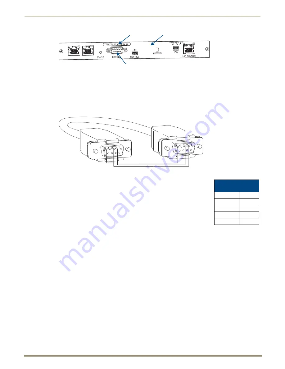
Attach a null modem serial cable without hardware flow control to the Control (DB-9 serial) port on the Enova
DGX Switcher. Use a null modem cable that matches the pin diagram below for RS-232.
Enova DGX equipment requires pins 2, 3, and 5 only.
2.
Attach the other end of the null modem cable to a PC.
3.
Use serial communication software to make sure the PC’s baud rate is set correctly for
the system. The recommended (default) settings for serial communication for Enova
DGX Switchers are listed in the table to the right.
4.
From the www.amx.com/products/APDiagnostics.asp website page (under AutoPatch
Tools on the right), click APDiagnostics and select Save to download the file.
5.
Optional – Select APDiagnosticsReadMe_x_x_x to read about the software before
installation.
6.
Click the application file (which is zipped).
7.
In the Compressed (zipped) Folders dialog box, click Extract All.
8.
Select a destination for the files.
9.
When the download is complete, click the application file and follow the directions in the installation wizard.
10.
Before using APDiagnostics, download and install the latest Bounds.ini file by clicking AutoPatch INI Updater
(also at www.amx.com/products/APDiagnostics.asp).
11.
Open APDiagnostics in Acquisition mode (default).
12.
Select Comm / Settings.
13.
Select the Serial Port tab and set the Comm ID and baud rate (9600).
14.
Click Accept.
Note:
DGX_SHELL commands are another resource for accessing diagnostic information for a system
(see page 235).
FIG. 115
Mac address label on CPU board
Control port
MAC address
CPU board
PC: DB-9
Enova DGX: DB-9
Enova DGX
Serial Port Settings
Baud Rate
9600
Data Bits
8
Parity
None
Stop Bits
1
Flow Control
None


