AMI Baby Voyager User's Guide
23
Step 7 Connect Cables,
Continued
C o n n e c t t h e S p e a k e r C a b l e
C o n n e c t t h e S p e a k e r C a b l e
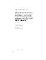
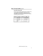
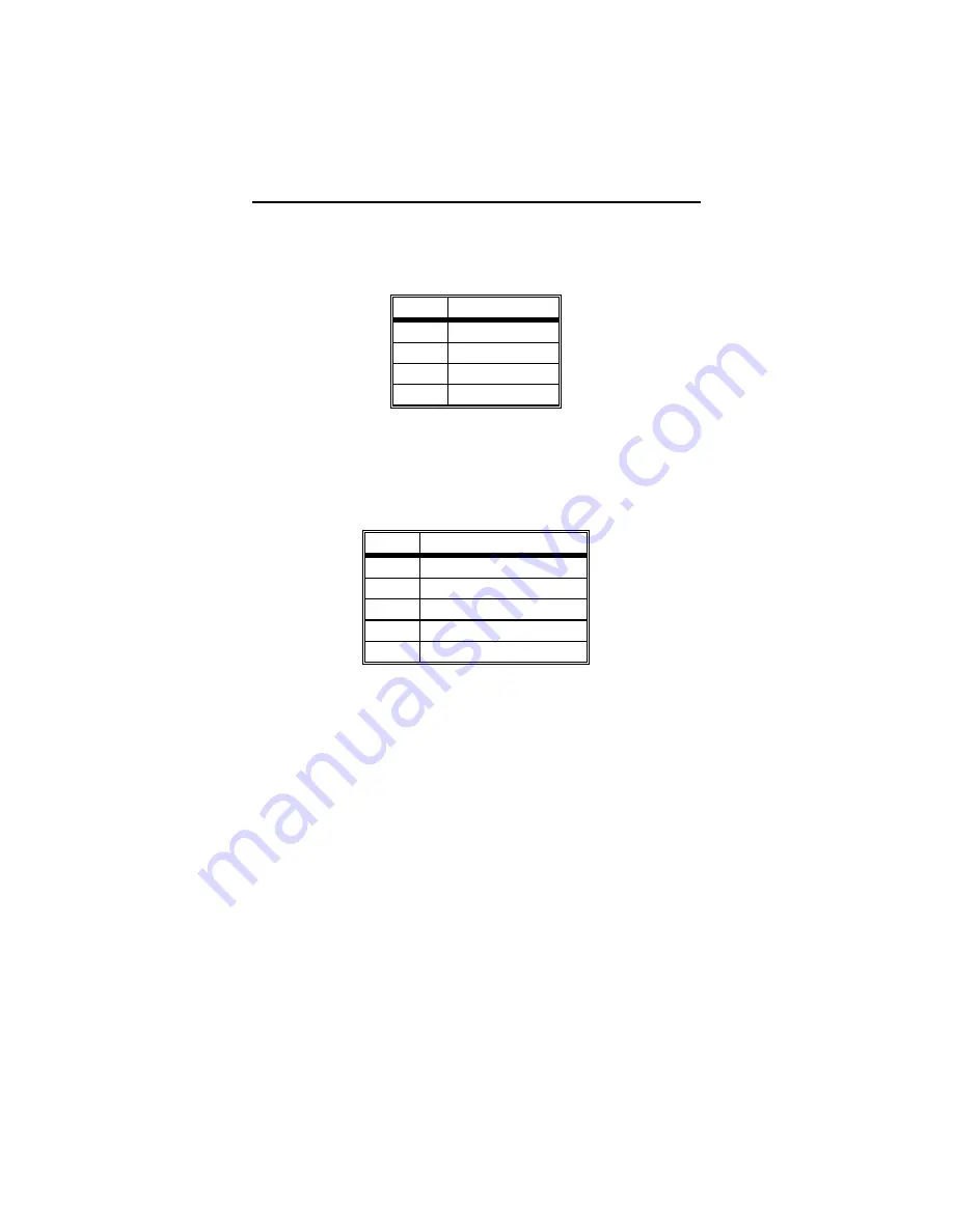
J13 is a 4 pin single-in-line berg. The AMI BIOS signals hardware
problems through the speaker. Pin 1 on the motherboard is labeled by
a plus (+).
Pin
Description
1
VCC
2
Key
3
Ground
4
Data Out
C o n n e c t t h e K e y b o a r d L o c k C o n n e c t o r
C o n n e c t t h e K e y b o a r d L o c k C o n n e c t o r
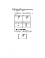
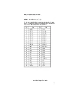
J15 is a 5-pin single-inline berg. The keyboard lock allows the user to
lock the keyboard, protecting the system from unauthorized use. This
connector is keyed with a blank hole. Pin 1 on the motherboard is
labeled with a plus (+) sign.
Pin
Description
1
LED power
2
Key
3
Ground
4
Keyboard Lock
5
Ground
J 2 3 T u r b o L E D
J 2 3 T u r b o L E D
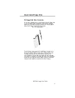
J23 is a 2-pin berg. The LED lights when the board is running at high
speed. Connect the Turbo LED to J23.
Содержание 39 Series
Страница 6: ...Preface vi ...
Страница 12: ...Chapter 1 Introduction 6 ...
Страница 14: ...Chapter 2 Installation 8 Baby Voyager Layout ...
Страница 26: ...Chapter 2 Installation 20 ...
Страница 69: ...AMI Baby Voyager User s Guide 63 ...

