AMI Baby Voyager User's Guide
17
Step 3 Install Coprocessor,
Continued
T e s t f o r M a t h C o p r o c e s s o r
T e s t f o r M a t h C o p r o c e s s o r
The AMI BIOS displays a System Configuration screen at the end of
POST. The math coprocessor is displayed here.
If the Installed message is not displayed, reinstall the coprocessor.
Switch off the power, check the orientation of the coprocessor, press
the chip firmly to make sure that it is fully inserted, and then power
the system up again. If you still get the same result, call AMI Technical
Services.
Step 4 Install the Motherboard
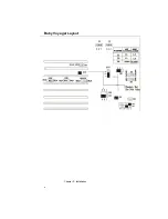
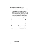
The mounting hole pattern on the Baby Voyager motherboard is
identical to the mounting hole pattern on the IBM XT motherboard.
Place the chassis for the Baby Voyager motherboard on an anti-static
mat. Connect the chassis to ground to avoid static damage during
installation. Connect an alligator clip with a wire lead to any unpainted
part of the chassis. Ground the other end of the lead at the same
point as the mat and the wristband. Rotate the chassis so that the
front is to the right, and the rear is to the left. The side facing you is
where the motherboard is mounted. The power supply is mounted at
the far end of the chassis.
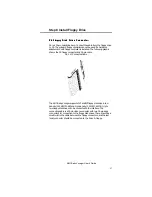
Push four nylon standoffs from the solder side of the motherboard in
the holes provided for them. The standoffs lock in place. Find the slots
provided for the standoffs on the chassis. Hold the Baby Voyager
motherboard, component-side up, with the edge with three standoffs
toward you, and the edge with the power supply connector away
from you.
Содержание 39 Series
Страница 6: ...Preface vi ...
Страница 12: ...Chapter 1 Introduction 6 ...
Страница 14: ...Chapter 2 Installation 8 Baby Voyager Layout ...
Страница 26: ...Chapter 2 Installation 20 ...
Страница 69: ...AMI Baby Voyager User s Guide 63 ...

