20 Gear Drive, Plymouth Ind. Park, Terryville, CT 06786
Tel: (860) 585-1254 Fax: (860) 584-1973 http://www.amci.com
Networked Indexer/Driver User Manual
C
OMMAND
M
ODE
D
ATA
F
ORMAT
83
Input Data Format
The correct format for the Network Input Data when the Networked Driver is in Command Mode is shown
below.
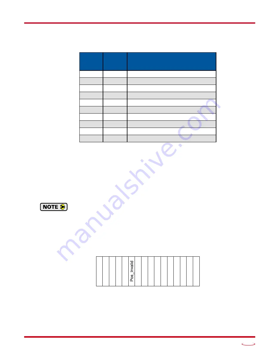
Table R7.21 Network Input Data Format: Command Mode
Format of Position Data Values
The format of the Motor Position, Encoder Position, and Trapped Encoder Position values is controlled by the
Binary_Input_Format bit in the configuration data written to the Networked Driver. (See
, bit 9 starting on page 64.) When the Binary_Input_Format bit equals “0”, the position val-
ues are reported with the bottom three digits of the value in the lower word (000 - 999) and the remaining dig-
its in the upper word. See
on page 67 for an explanation of this format.
When the Binary_Input_Format bit equals “1”, the position values are reported as 32-bit signed integers, with
the location of the least significant bits dependent on the selected endian format.
The range of values when using the multi-word format is -32,768,000 to 32,767,999. When
used in continuous rotation applications, such as control of a conveyor belt, it is possible to
overflow these values. When any of the three position values overflow, the value of the associ-
ated data words will become indeterminate. AMCI strongly suggests using the signed 32-bit
integer format for continuous rotation applications.
Status Word 0 Format
Figure R7.4 Command Mode: Status Word 0 Format
Bit 15: Mode_Flag –
Set to “1” if in Configuration Mode, and set to “0” if in Command Mode. The Net-
worked Driver powers up in Command Mode and shows a configuration error. The Networked
Driver will not power the motor or accept commands until a valid configuration is written to it.
Bit 14: Module_OK –
“1” when the Networked Driver is operating without a fault, “0” when an internal
fault condition exists.
EtherNet/IP
or PROFINET
Word
Modbus/TCP
Register
Command Mode Input Data
0
0
Status Word 0
1
1
Status Word 1
2
2
Motor Position: Upper Word
3
3
Motor Position: Lower Word
4
4
Encoder Position: Upper Word
5
5
Encoder Position: Lower Word
6
6
Trapped Encoder Position: Upper Word
7
7
Trapped Encoder Position: Lower Word
8
8
Programmed Motor Current (X10)
9
9
Value of Acceleration Jerk Parameter
Status Word 0
15 14 13 12 11 10 09 08 07 06 05 04 03 02 01 00
Mode_F
la
g
Modul
e_O
K
Conf
ig_Er
r
Command
_
E
rr
Inp
u
t_Er
r
W
ai
t_
Assy
S
e
g
In
_As
sy_Mo
de
Move
_Cm
p
D
ec
ele
rat
in
g
A
cc
ele
rat
in
g
At_Home
Stop
ped
In
_Hol
d_St
a
te
M
o
v
in
g_CC
W
M
ovi
ng_
C
W
Содержание SD17060E2
Страница 1: ...MICRO CONTROLS INC ADVANCED U s e r M anual Manual 940 0S172 E2 Technology E2 Technology...
Страница 10: ...ABOUT THIS MANUAL Networked Indexer Driver User Manual ADVANCED MICRO CONTROLS INC 10 Notes...
Страница 22: ...UL CUL RECOGNIZED INSTALLATIONS Networked Indexer Driver User Manual ADVANCED MICRO CONTROLS INC 22 Notes...
Страница 54: ...CALCULATING MOVE PROFILES Networked Indexer Driver User Manual ADVANCED MICRO CONTROLS INC 54 Notes...
Страница 88: ...COMMAND MODE DATA FORMAT Networked Indexer Driver User Manual ADVANCED MICRO CONTROLS INC 88 Notes...
Страница 106: ...INSTALLING AN AMCI NETWORKED DRIVER Networked Indexer Driver User Manual ADVANCED MICRO CONTROLS INC 106 Notes...
Страница 130: ...ETHERNET IP EXPLICIT MESSAGING Networked Indexer Driver User Manual ADVANCED MICRO CONTROLS INC 130 Notes...
Страница 134: ...MODBUS TCP CONFIGURATION Networked Indexer Driver User Manual ADVANCED MICRO CONTROLS INC 134 Notes...
Страница 144: ...LEADERS IN ADVANCED CONTROL PRODUCTS ADVANCED MICRO CONTROLS INC...


