Instruction manual 91/104 V9.2
Commissioning
5 Commissioning
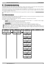
The PWM3D digital drive comes standard with an LCD display to display various information and internal states (alarms, parameters,
settings) and four keys that are used to navigate the internal menu or change the various parameters.
The parameters and alarms are written on the display clearly (in English) and it is therefore not necessary to have the instruction
manual at hand to identify them. The menu is structured with a tree and allows a simple and intuitive navigation: the various paramet -
ers are grouped according to their function.
The PWM3D digital drive can be set and calibrated directly using the built-in keyboard and display and it is not necessary to use a
PC.
5.1 Menu structure
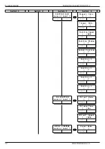
The following drawing indicates the tree structure of the PWM3D drive menu. As you can see the structure can reach up to 4 levels of
depth and the various menus are grouped from a main menu.
Some menus can only be displayed when using a certain type of transducer, or if an optional card is mounted.
Each menu is made up of 3 different zones:
1. At the top
indicates the inscription that will be read on the display. At the point where “[...] " is indicated, a letter will appear
which can change based on the value of the parameter displayed.
2. At the bottom left
indicates the original standard value of the displayed parameter.
3. In the bottom right
there is a space available to the customer to note any changes in the displayed parameter.
NOTE:
If an indent “- " is present in the zones indicated in points 2 and 3, it means that that parameter is not modifiable.
NOTE:
Menus with an asterisk (*) on the side indicate a parameter that may have different values depending on the selected
speed range (Stage 0 or Stage 1). If you use the “Electronic Gear Change " function, the parameter value for each selected range
can be noted in the appropriate table on page 69.
Level 1
Level 2
Level 3
Level 4
QUICK SETUP
menu at level 1
-
-
MOTOR PARAMETERS
menu at level 2
-
-
SELECTED GEAR
[...]
-
-
MOTOR TYPE
[...]
LowSpd
*
NOMINAL VOLTAGE:
[...]V
0
*
CONT.SERV.CURR.:
[...]A
0.0
*
MAXIMUM CURRENT:
[...]A
0.0
*
NOMINAL FREQUEN:
[...]Hz
0.0
*
MOTOR POLE
[...]
0
Alter Elettronica s.r.l.
21


