Instruction manual 91/104 V9.2
Commissioning
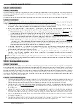
9. When you have finished all the procedure indicated and the motor runs well with the Slow Range (Stage 0), you must stop
the motor and disable the drive (DEN = off). Save parameters in FLASH memory.
10. Select the Fast Range (Stage 1) with the digital input. Check the switching of contactors.
11. Set the parameters individually or copy the parameters of the Slow Range as a starting base. To copy the parameters from
Stage 0 to Stage 1, use the menu “Advanced Setup → Aux Function → Elec.Gear Change → Copy from Stage0": Press
the
button “► " which shows a “
“ in the bottom left corner, then press the Key “▲”,and after a few moments the inscription
“OK " appears to indicate that the copy has been made. Now you can only change the different parameters between slow
range and fast range.
12. Follow once more the procedure
indicated in paragraph "Calibration and adjustments“ from page 57.
13. When you have finished all the procedure indicated and the motor runs well also with the Speed Range (Stage 1), you must
stop the motor and disable the drive (DEN = off). Save parameters in FLASH memory.
14. At this point the drive is calibrated on both speed ranges.
5.6.8.3 Table of parameters
The following table is used to annotate the value of the parameters that change when selecting Stage 0 or Stage 1. The parameters that
will be written here should not be written in paragraph "Menu structure“ from page 21. The empty fields mean that the parameter is
equal to the value of “default ", so it has not been modified.
PARAMETER NAME
DEFAULT
STAGE 0
STAGE 1
Motor type
Async. LowSpd
Nominal Voltage (V)
0
Continuous service Current (A)
0
Maximum Current (A)
0
Nominal Frequency (Hz)
0
Maximum Speed (Rpm)
0
Maximum Voltage (V)
0
Max. Speed at Nominal Power (Rpm)
0
Nominal Speed (Rpm)
0
Magnetic current (A)
0
Stator resistance (ohm)
0
Magnetic inductance (mH)
0
Leakage inductance (mH)
0
Speed loop P gain 1
20.0
Speed loop P gain 2
20.0
Speed loop I gain 1
0.20
Speed loop I gain 2
0.20
Speed loop gain scale (%)
10.0
Current loop P gain
0.60
Current loop I gain
0.005
Flux loop P gain
4.0
Flux loop I gain
0.01
Speed ramp time (Sec)
60.0
Table 3: Parameters modified with the electronic gear change
5.6.8.4 Tips for contactors’ command
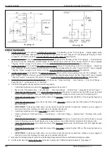
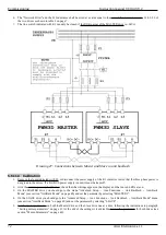
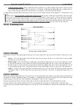
As indicated in drawing 25 and drawing 26, contactors used to switch motor windings can be controlled directly by the drive using a
24Vcc relay with exchange contact connected to the digital output set in paragraph 4. In this way the PLC or CNC only has to control
the digital input that controls the speed range change (the one set in point 1).
It is also necessary to connect a normally open contact of these contactors to two digital inputs of the drive.
Alter Elettronica s.r.l.
69


