Instruction manual 91/104 V9.2
Installation
1
PTC-RES-
Connect the thermistor mounted to the resistors of external clamps, otherwise leave the bridge connected (only
for PWM3D-000).
2
PTC-RES+
3
PTC-MOT-
Connect the thermistor mounted in the motor.
NOTE: this contact is also available in the X4 connector.
4
PTC-MOT+
4.4.2 Connector X4
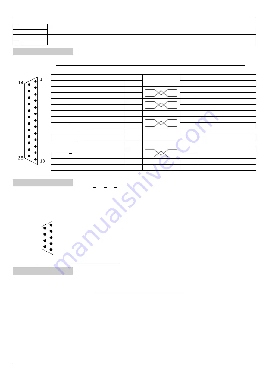
Connection of the transducer “Encoder TTL” mounted in the motor. The connection cable must be shielded and the shield must be
grounded on both ends. If a transducer connected to the X14 connector is used, then this connector must remain free and unused.
Assigning connector PINs:
Drive (Connector X4)
CONNECTION
motor
SIGNAL
N. PIN
N. PIN
SIGNAL
+5V (positive feeding encoder)
1
0V (Power supply 0V encoder)
2
Channel “A " encoder
3
Channel "A“ encoder
4
0V (shield pair A + A)
5
Channel “B " encoder
6
Channel "B“ encoder
7
0V (shield pair B + B)
8
PTC probe in the motor (signal)
13
──────────
0V (pair Z + Z)
16
Channel “Z " encoder
17
Channel "Z“ encoder
18
PTC probe in the motor (0V)
25
──────────
0V (cable shield) – Connector box
View of the Flying connector type “D " 25 poles female on the soldering side.
4.4.3 Connector X5
On this connector are available channels A, A, B, B, Z, Z of the TTL encoder connected to the X4 connector or a simulated encoder if
you use a transducer connected to the X14 connector and in this case you can select the simulated encoder type (see paragraph
"Emulated encoder“ on page 56).
The connection cable must be shielded and the shield must be grounded on both ends.
Assigning connector PINs:
1
5
6
9
N. PIN SIGNAL
1
Channel “A” encoder
2
Channel ”A“ encoder
3
Channel “B” encoder
4
Channel ”B“ encoder
5
Channel “Z” encoder
6
Channel ”Z“ encoder
9
0V
View of the Flying connector type “D " 9 poles male on the soldering side.
4.4.4 Connector X6
Connection analog outputs. Voltage ±10V max or 0-10Vcc max. – Output resistance 1K
.
More information can be found in para-
graph ”Analog Output X“ on page 42.
Always use good quality shielded cables and connect the two ends of the
shield
to the ground
. On the drive case, near the connectors,
anchorages are available for screens (see Mechanical characteristics page 85).
Signal allocation to PINs:
1
A0V
0V analog. The analog 0V is connected to the drive case.
2
AO1
Analog output 1 programmable.
It is normally used to provide a voltage signal proportional to the load on the motor.
3
AO2
Analog output 2 programmable.
It is normally used to provide a voltage signal proportional to the speed of the motor.
4
AO3
Analog output 3 programmable.
It is normally used to provide a voltage signal proportional to the motor torque.
5
AO4
Analog output 4 programmable.
Normally it is not used.
Alter Elettronica s.r.l.
15


