Diagnostics
Instruction manual 91/104 V9.2
6.4.5 Auxiliary Supply Fault
This alarm appears when auxiliary power voltages are lower than allowed.
The causes that generate this alarm are:
1. Reductions in the supply voltage of the services.
2. Overload or short circuits on the output 24Vc.c.
In this case check:
•
Control the supply voltage of the services.
•
Check the current on the 24Vcc output.
6.4.6 Charge Fault Bus
This alarm appears when the DC BUS voltage does not reach the right value within a certain time. In this case check:
•
After eliminating all power voltages (services and power), disconnect any electrical cables connected between DC+ and DC-
terminals and check that they are not short circuited.
•
If the DC+ and DC- terminals have no cable connected, there is likely to be an internal failure of the drive. Contact the AL -
TER Technical Office.
6.4.7 Capacitor Over Temperature
This alarm appears when the temperature of the capacitors on the D.C. Bus higher than allowed.
The causes of the alarm are:
1. Temperature inside the electrical panel too high.
2. Insufficient internal ventilation of the drive.
3. Heavy use of the motor.
In this case check the proper functioning of the cooling fans or air conditioners of the electrical panel.
NOTE:
If the motor is used harshly, it may be necessary to mount an optional “capacitive module " outside the drive (our module
13/007).
6.4.8 Clamp Overload
This alarm appears when the resistance of the internal clamp to the drive has exceeded the temperature of 135 °C.
The causes of the alarm are:
1. High number of consecutive motor stops.
2. Stop times too short.
3. Load inertia too high.
4. High number of consecutive accelerations and decelerations of the motor.
5. Incorrect defect or fitting of the transducer mounted on the motor.
6. Speed loop instability.
Operations to be carried out:
•
Reduce the performance of the machine.
•
Check the size of the drive.
•
Use a larger drive.
•
Use external resistance to the drive.
•
Adjust the time constants of the speed loop.
•
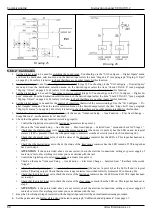
Check the X3 connector
(see paragr. 4.4.1 at page 14):
◦
There must be a bridge between PINs 1 and 2, if you do not use a thermistor on the external clamp resistance.
◦
Any thermal probe in the motor must be connected between PINs 3 and 4, or these pins may be left empty.
Notes:
More information is available in paragraph ”Clamp resistor“ on page 14. In case of need contact the technical service ALTER
to size the external resistance.
6.4.9 D.C. Bus overvoltage
This alarm appears when the DC BUS voltage exceeds the maximum allowed. In this case check:
•
If an external clamp resistance is used, check that the circuit between the Rest+ and R- terminals is not interrupted.
•
In case of use of the internal clamp resistance to the drive, check that the bridge between the Rint+ and R- terminals is moun-
ted (see drawing 1 on page 11).
78
Alter Elettronica s.r.l.

